Thursday, December 18, 2014

1.2V Emergency Light Revisited

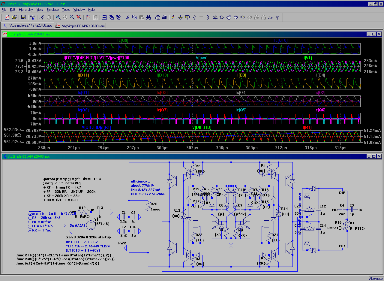
i've built several of these bullsh¡t -- the only one that seems to function fine not been taken back appart to spares -- it goes from 1 AAA about 24h , perhaps more , then simultaneously restarts at low battery after being "mute" at some 36h after initial 24+h time of operation , then it works barely visible next 24+h - - i guess (for obvious reasons i haven't just sat and watched what it exactly does) -- the grid :: (R2 here is to match the BC847 to a real KT315 ) the measured operational data :: avg. 1.4415V (40...50 assume) 47mA @ input terminals , avg. 5585mV(28.5...28.7mV @ 10.3Ω res. = ) 2.7767mA @ "High" voltage terminals - gives us apx. 22.3% efficiency in NRG2NRG and 11.2% efficiency in NRG2Light --- the blue light being well detectable gives here the effect of "successful" design (& sh¡t ...)                 ... so revisited v. :: ◄ that thing matches the real "GO" better than the previous simulation -- apx. measured / derived operational data :: 1.472V ~47mA @ input terminals , 8.37V 4.59mA @ "High" voltage terminals - gives us apx. 55.5% efficiency in NRG2NRG and 27.8% efficiency in NRG2Light --- there is no experimental data yet about the responce to an input power variation (just wanted to verify such works)

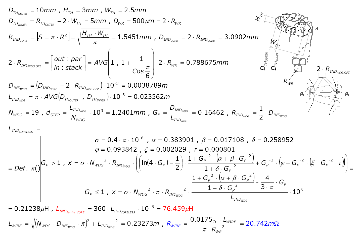
Confirming that the "guess" value used for inductor in the last DC-DC converter does not fall too far from the actual 1 ... ◄ about
xSpiceComputed-!- Error
Inductance60µH76µH68µH ± 12%
Resistance980mΩ*
(39mΩ)
21mΩ30mΩ ± 30%


* -- assumed / defaulted to - diameter 0.1mm* (corrected for 0.5mm)
-!- -- the error is given so because there's no data about the real values (should be derived experimentally)

some changes :: ... usually there's not enough power to push the power transistor ...

(Added 2015-01-10) LTSpice Src ...

[EoF]

Saturday, December 13, 2014

Switching TEST draft

Blah , i don't get the sh¡t ...
... U can't use N avalanche FET coz it ?? closes impossibly slow (kills efficiency) ... ... so increasing the fq. enables smaller steps less output waving . . . but also requires higher power driving (less efficiency) ... + THAT cfg./concept does not like inductors

1.2V inverter again

The goal :: is to define / design a low power logic for abstract use in powering by "empty" 1.2V batteries

In common the loaded 1.2÷1.5V battery keeps it's terminal voltage above 1.0V , internal resistance - fresh ... "empty" 250÷500mΩ ... 750÷1250mΩ (varies more by battery type and less by manufacturer -- should be measured for specific application)

If the internal resistance goes beyond "1250"mΩ (very apx. value for critical Lim.) it starts rising fast and also the battery's unloaded terminal voltage starts to drop significantly dn2 0.9÷0.8V (◄ below that the battery can be used as - say a 1 minute - to load the capacitor to 550÷770mV and then switch that charge somewhere)

So the secondary use for batteries can be the "central" "dropping voltage" mode - unloaded terminal voltage 1.13 ... 1.0 V output current 20 ... 1mA - thus - the supplied power 23 ... 1.0 mW . . . so if you "define" a mW application such can still work several hours

Back to inverter - the graphs. ::


about ::
  • The simulation is verified for 0.9 to 1.9V to be operating as expected
  • It is normal to expect for the fast counters not to go over the 1-10th of their simulation frequency
  • It is also normal to expect they wont go at any frequency (coz the collector resistance , output load capacity , other ...)
  • ... otherwise it'll draw some 14µW at 1.2V UCC - in other words - ! 1mW supply can push 1000 : 14 = 71 inverters OR 35 RS-triggers (/ D-triggers) OR 12 C-triggers (a 12 stage counter/divider) ►►
  • ►► since you have to select the similar-ß BJT-s and to tune 3-shold for each inverter - then - it's impractical to build anything based on components that inverter's TEST prototype here has


▲▲ the entire bullsh¡t is required to pre-calibrate my system before an attenpt to do something with something2 called "Electric VLSI Design System" -- so as i proceed in an unusual way - the 'log 's provided in case any sub-grid of this insanity 'd B a pt. of interest . . . 3,2,1,OFF

Monday, December 1, 2014

RS-3-ger counter

as teh prev.(post's SCS) does not like the 1.2V we've 2 2 the dev. steps 1-ce again ::


uses/tech. 2N3904 1N4148

about -- http://chpsndtch.blogspot.com/2014/10/lets-put-some-sht-up-eg-weird-science.html -- an area to collate the "science" on

Saturday, November 29, 2014

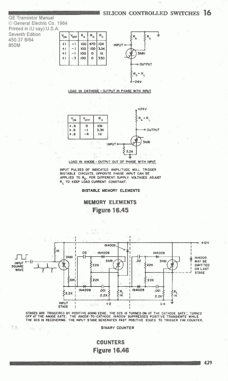
Re SCS(SCR) Counter

extends the post http://chpsndtch.blogspot.com/2014/11/scs-counter-sw-d-capacitor-led-single.html
probing the switching modes ::
an attempt to extend down the supply range ::
likely an impractical success ::

Saturday, November 22, 2014

1.2V experiment

This shit has survived the output short circuits for so far // the lucky idiot stands for clear current path through PN junctions to ground /!\ the LT Spice seems to overlook such condition !!! and simulates "fine" - as if there were large resistance in series with PN junctions ??? - so you have to pay extra attention your currents will take the realistic values ...

otherwise it's quite stable (* the 11-th v. of this particular) 1.2V supply (i have no scope so you'd like to check it for possible noise) drawing some 6mA - which i find too excessive for 6LF22 so i likely'll convert something out of these for replacement - if they run even close to what they simulate(*) ◄ this one is a design concept and likely has inacceptable dependency both on load and on supply

... so much for supplies - thanks to "1-st" i was able to check the "performance" of the various "discreet" logic inverter concepts ...

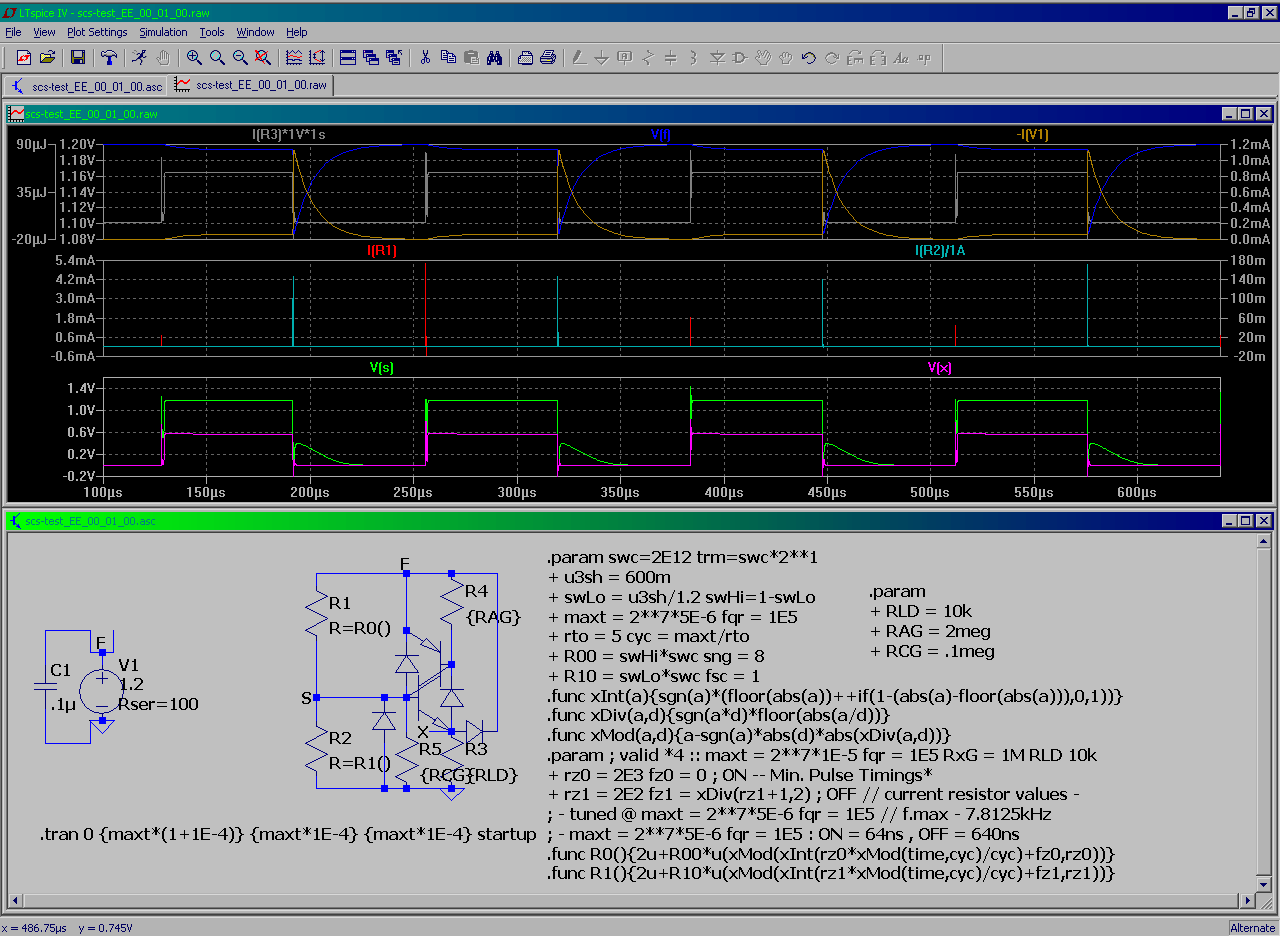
and some more (this bullshit editor is really great) i like the 3-transistor 1-s (( but it's tricky to get them generating the Sq.Wv at that current mode // + it'd take a lot of components (to test verify and threshold match e.c. , e.c. ) to get - say - slow A/D converter built from )) - the next comes is 2D+2R base-shunt MP42 v. but it also doesn't want to oscillate too well - the last 1 (the lowermost in the last graph) has only 1 stage built - so i donno about it yet (perhaps i should yet rise it's threshold level before testing the Sq.Wv generator -- otherwise the varying ß may cause problems ... )

/// the graphs are normalized to all meters' average - V.max " = V.supply ' = 1.2V ' " - during the measurement - so they contain systematic errors - depending of the set of multi-meters used (likely is the same for the same "type" of inverter)

Monday, November 3, 2014

SCS Counter + SW-d Capacitor Single 1.5V-cell LED Driver

(none of the following is not yet tested in practise - - you have to match the average currents @ critical chains , in case of a failure the grid should be redesigned to lower or higher currents or conceptually redesigned - - there might be some combinations / features - that never work in practice or won't ever work as good as required - that are hard to foresee)

Re-ranging SCS on a different component base ::


"Simple" circuit that suppose to run from single Ag-cell up to AA


[EoF]

Sunday, October 26, 2014

Switched inductorless DC→DC converter TEST

the TEST trg./src.at (fig.1) got my interest by it's switching capacitor name values (1µF) v. V.OUT parameters -- I.max = 50mA U.TOT = 30V . . .

. . . the simulation showed that the transistors at the same "shoulder" are OPEN @ the same (short) time + the generator wave forms were somewhat not that you'd expect

(i guess presented in the ® order ) the figures show the improvement/TEST steps - to meet proposed OUTPUT parameters to this 9V : 30V converter

note : the peak currents approach 1A range - the averages - are the way over the specs of the 1-s of the initally shown* transistors (in test the 2N3906*,-04* was used to get the oscillations started) /!\ -- you likely can't build any of the shown grids ( using these* transistors ) that would survive the switch ON + further more (i suppose) using the 6LF22 / 6LR61 or alternate won't meet the power demand of "this" converter the 6x AA / LR6 or better is more realistic


Figures ::
  • Fig.1 :: the ® - a lot of question marks
  • Fig.2 :: 68% OUTAVG 28V 51mA INAVG 8.4V 250mA
  • Fig.3 :: 64% OUTAVG 25V 44mA INAVG 8.5V 200mA
  • Fig.4 :: 74% OUTAVG 29V 51mA INAVG 8.4V 230mA
  • Fig.5 :: 79% OUTAVG 35V 63mA INAVG 8.3V 340mA
  • Fig.6 :: 74% OUTAVG 38V 43mA INAVG 8.4V 260mA


Fig.1

Fig.2

Fig.3

Fig.4

Fig.5

Fig.6


[EOF]

Thursday, October 9, 2014

... Let's put some sh­¡t up e.g. the weird science about MEM and SCS/SCR

What's good about the Blogger if you dont blog , ? yes.

(re-)starting with a lot of diodes 1N4148 + 2N3906 , 2N3904
trying 2-def a microbe-hour csc flip-flop
... it's below the lower half of the kHz range
to induce re triggering - takes deviating from std.
about 170 Hz operation (amazingly valid for full possible supply range ???)

teh prev. "defined" crash-ware (oldies)
Bench for a single stage
~ about 30kHz op.-s
. . . . . . . . . i finally get this memory cell working . . . . . . . . . 20kHz write (with ultra cool power draw)
. . . WHAT WAS UPLOADED WAS 2048x1512px133KB(136733bytes)
WHAT YOU ARE LOOKING AT IS
1600x1181px263KB(268929bytes)
??? -- SORRY I GOT IT WRONG AGAIN SO GOOGLE HAD TO "FIX" IT - g.d. perverts - they just can't leave anything untouched . . .
. . . ok, (it's just) yet another totally unnecessary "optimization" by Google ________ come on it's just a few lines to add to your server code (run 1-ce(onece) per img. upload) to tell whether you managed to increase

1-st - the i-net bit traffic on each(every) future page request
2-nd - thus everyone elses' wait time (making i-net slowwer)

 . . .ok that's about how fast we runn off the fossil fuels , but

 ? what i suppose to do ? chk each time if my img.-s're ok ?? and if not
 ? split'em into smaller frames ,
 ? write extra code for each frame
 ? (uploading 4 images (3 extra file headers) instead of 1)
???? delete the "not successful" upload from "blogger album" (takes to wait all blog images to load b4 you can delete any particular 1 OR navigate from 1-st to requred to delete 1) - in "one word" make a day full of job out of what should've taken 2 minutes

why i always have to take a day free to uplaod single image - IT JUST SO ABSURD AS IT IS

 . . . sorry i don't need to purpose my salary to figure out another "virtual task" - i don't get your game to be honest (perhaps you're just stupid or smth. out of my reach)

this is not a ready to use stuff
a snapshots from on going research dev.
it's like @ this Z-up  the grid does THAT
[eof]

Monday, October 6, 2014

Flip-Flops' Speed TEST

those things are most always required fast , so . . .


. . . 3 , 2 , 1 , exit *

Excel v. LTSpice

since the decoder's quite complex (and unoptimized) then , to avoid unnecessary head ace , i QC-d it's operation on "spreadsheet model" , the head ace however started with defining the OC functionality in Switcher CAD - which i donno about if it's fully ok the way it finally got implemented ...

/!\ -- pay attention to the R3 to R3 ratio in macro model ↓↓ and in test ↑↑ circuit (before you use this feature in your own simulation) -- /!\

... a digital head ace ::


[EOF]

Wednesday, October 1, 2014

Tuesday, September 23, 2014

Random Test

LM324A , uA776 , LT1366
LTC6081 , LTC6241
LT1211 , LT1677 , LT1884
LT1881 , LT1813 , LT1360
LT6014 , LTC2055 , LT1097
AD8628 , LM324 , LT1012 NEW!
AD8628 , LM324 , LT1012 , LT1097 NEW!
Swimming course - ? whitch way is the shore
AD8628 , LM324 , LT1012 , LT1097 NEW!
IDEALISTIC TEST
AD8628 , LM324 , LT1012 , LT1097 MORE
ABS Zero TEST
AD8628 , LM324 , LT1012 , LT1097 MORE
APP TEST
AD8628 , LM324 , LT1012 , LT1097 MORE
APP TEST - zoom in

just a draft test for the 2-clones on the first image - /!\ it's (the test's) not scientifically designed - there's much nothing to conclude about it /!\