Showing posts with label Current limit. Show all posts

Thursday, March 14, 2019

Progressive current limiting

Figures ::


Legend :: opamp.Q1 mirrors the current at R5 , opamp.Q2 limits the current progressively ... and incase of the SC it cuts the output the more off the lower is the output voltage -- so there's double level progressive limiting (the fig.2 shows the 1-st and the fig.-s 3 to 5 show the 2-nd - a short circuit - limiting levels) . . . the resistor values for R24 to R26 and R21 , R22 , also for the R14 may need to be adjusted to get the real build of the circuit stable (maybe it takes more adjustments -- but these are known to be more likely critical at this stage of dev.)

[Eop]

Monday, January 14, 2019

regulated switched LED regulator designs (experimental)

the thing ::


how to set it up in practice . . . involves a number of tests ::

  1. Detach the mosfet and the feedback Mod line -- from simulation and from build
    Regulate the frequency and duty to match those of the simulation
  2. Re-attach the mosfet , ( /!\ /!\ /!\ ) set some 20Ω or greater in series with the 6LF22 to limit the current through LED-s --and-- set electrical fuse or limitting resistor in series with the LED-s --or-- double the number of LED-s ( /!\ /!\ /!\ ) - - - - - - - - - we are going to verify the transformer ::
    do the same mods on the simulation and test for the differences . . .
    -- if the real build performs worse you need to recalculate and rebuild the transformer accounting for resistance not present in ↑this↑ circuit
    -- if the build performs better then the primary side is "over-driven" the timing of the switching wave-forms has to be re-evaluated and adjusted
  3. Attach the Mod line --and-- ( /!\ /!\ /!\ ) set the regulation to be greater than in simulation (!! dont remove electrical fuse or extra LED-s !!) ( /!\ /!\ /!\ ) ,
    -- regulate it bit below the desired LED current (in case the regulation failure -- the regulator has to be re-designed --or-- replaced with better known one)
  4. if everything worked out so far the additional tests are required such as ::
    • test for bit higher than simulated input voltage (the Cl batteries may have up to 1.8V per cell e.g. 10.8V for fresh 6LF22)
    • test for battery contact strobe !!!
      -- here everything can fail -- use fuses and perhaps build a protective controller that can fast switch off the circuit under test
    • test for the lower than in simulation input voltage !!!
      -- may result in oscillations failure and the MOS-FET being "constantly ON" (attempting to remain in conduction mode) . . .
    • etc. ...

Basic simple ::


add VCO , Mod2 divider , the 2 to 4 decoder and a current sense / +integrator -- and it's basically done . ..


[Eop]

Friday, January 11, 2019

2019.01.05 follow up . . .

. . .

6.1 ) -- basic , simple -- Op-Amp v. NPN input stage (using macro-/"net-list" -model)


6.2 ) -- basic , simple -- Op-Amp v. NPN input stage (using component level model)


6.3 ) -- basic , simple -- Op-Amp v. NPN input stage (using component level model)

( ↓the mod↓ incase the ↑prev. v.↑ don't want to start up "simultaneously" )


[Eop]

Tuesday, December 26, 2017

the Actual/Built LED verifier

as i was not about to build a PCB for this the sot-jFets were not used . . .

Spice design ::

Real build ::


[Eop]

Thursday, February 9, 2017

some experimental 1.2V supply designs + rnd. osc. variant

Originally designed for 3-5V operation , also studied for 1.2V
as with the 555 --  the basic operating mode's to generate low duty pulses -- economizing the battery


 Hi precision supply -- preserving near ® precision and with added current limit


Simple not limited 1.2V linear voltage regulator


the Op Amp variant of the above " Hi precision supply" without current limiting
-- the design has a "new" type of adjustable voltage reference that has not especially been optimized nor tested for varying operating conditions !!! (i just needed one and simple here !fast (as in common))


+ some more : update 2017-02-13 (1-st time to break the ±1µV error !?)


[Eop]

Friday, November 11, 2016

yet another 1.2V supply

Dif. Amp. Draft design:


Dif. Amp. to Op. Amp. - with overshoot shunt:


New concept with a short circuit limit and indication:


[EoP]

Saturday, July 9, 2016

rev. +1.2V Linear Voltage Regulator with Current Limit

not built in real yet /!\ e.g. possibly no reverse pol. prot. + unknown amount of spec. not handled states ...

[Eof]

Wednesday, October 14, 2015

a Collector load (sc proof) Vtg. Regulator

since the component countfor this bullsh¡t


is higher and it has an error to the range
 of the following (! not built / tested -- but i guess it's not far from it´s actual)


then i guess i gonna get this 1 PCB-d and cased in with an appropriate ( 300+mA @ 10V DC ) transformer , damn it takes long to test out what you actually need and that actually works as designed -- should've brought a random 600÷1000mA 9V SC proof linear reg. such as KA7809

Update !


now more precise v. of the above is available


[EoP]

Sunday, April 19, 2015

Simple Current Limits Compared (Updated!)

Type.1

Type.2

Update !!!
► emerged by the predecessor of the second from the right - a "constant current shunt" - that was the best performing such in one of the experimental linear regulators (now revisited)see also :: yet another constant current source

Friday, April 17, 2015

Regulator Redesign (/Lab -- as always . . .)

________________________________________________
2015-04-15 ::
¯¯¯¯¯¯¯¯¯¯¯¯¯¯¯¯¯¯¯¯¯¯¯¯¯¯¯¯¯¯¯¯¯¯¯¯¯¯¯¯¯¯¯¯¯¯¯¯
 . . . trying to "de(/un)-bug" the last design from prev. post -- normalize power range , minimize the error . . .

+ a modified v.'s foldback diagram


Customizing/"improving" the 78Lxx for 1.2V

i only guess it's 3.0V
________________________________________________
2015-04-16 ::
¯¯¯¯¯¯¯¯¯¯¯¯¯¯¯¯¯¯¯¯¯¯¯¯¯¯¯¯¯¯¯¯¯¯¯¯¯¯¯¯¯¯¯¯¯¯¯¯
"Minimizing Compile" , exploring the switcher mode v. , experimenting with foldback . . .

thought to use the LT's µ-P 2.5V LDO -- but the 3uA is likely causing it's instability in high loads env.


________________________________________________
2015-04-17 ::
¯¯¯¯¯¯¯¯¯¯¯¯¯¯¯¯¯¯¯¯¯¯¯¯¯¯¯¯¯¯¯¯¯¯¯¯¯¯¯¯¯¯¯¯¯¯¯¯
Optimizing "Design"

Update! :: the foldback re-visited . . .
Update+ :: ±10µV version ::
Update+ :: ±12µV version with foldback updated to support high load capacities (no frequency test - what so ever- carried out + i donno how to thermal compensate - /!\ so i never do /!\) e.g. you have to recalculate the design before any attempt to assemble it

________________________________________________
[EoP]
¯¯¯¯¯¯¯¯¯¯¯¯¯¯¯¯¯¯¯¯¯¯¯¯¯¯¯¯¯¯¯¯¯¯¯¯¯¯¯¯¯¯¯¯¯¯¯¯

Saturday, January 10, 2015

Random Voltage Regulator Tests

Random keywords : stability, efficiency, ripple, startup time, slew rate, deviation :::


(Added 2015-01-10) LTSpice Src ...

[Eof]

Sunday, February 2, 2014

Re - Custom Simple Linear Regulator

(extends:: Custom Simple Linear Regulator)
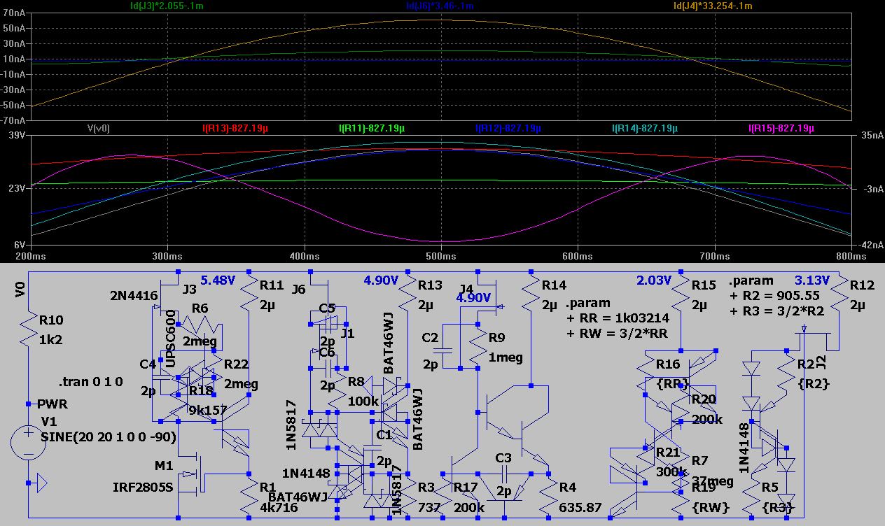
i may be an idiot but most voltage regulator circuits i've come across in internet appear to be too unstable or of not enough range for design target when simulated !! (usually the simulation appears to be the way batter quality than the real life build) so not enough range in simulation - is this for any use

so a bit of my research history on this subj. ::

first i thought that for successful design of a voltage regulator is required a good voltage reference ...

it may be that way but the precision voltage reference alone does not define a thing - more important is what you do with it or other words how you utilize it with respect of the rest of the circuit - so it turns out you can "define" your voltage without any specific voltage references - in the following test ::


the R4 is required for the simulation to run (for the circuit to be defined in the Solve Electric) -- i guess i added the diode for a zener - anyway this modified constant current source turns out to be very precise comparator for external voltage ::


wow -- a bad example -- anyway 1 of my early struggles -- the "comparator" is formed here by Q5 Q6 (Q9) if the TVP (test voltage point) increases the Q6 and Q9 start to open cutting off the Q11 ((?? all this for voltage reference ?? for precision constant current by J1 J-fet ... wow XD)) . . . so the Q1 has ??? high precision voltage on it's base and if PF gets too high the emitter-base current of Q1 reduces reducing the darlington's - Q2 Q10 - current - which in turn maintains PF in required limits - the circuit was never built as i found it too "expensive" or time consuming (along with tuning the real thing)

here's the latest zener ::


and what it's good for ::


???? -- running a scratch supply concept and testing various features -- everything is cool ? ? ? but to get only 20mA usable power (and who gonna build that . . . i'm out XD)

...

an alternative to a grid shown in ® Custom Simple Linear Regulator ::
the minimalist concept::


and minimal cfg for practical usage (the specs on the lower simulation do not apply to this grid - look the plots) -- doing the over current limiting here was a bit tricky


[EOF]