Showing posts with label SCS. Show all posts

Thursday, April 11, 2019

Latest experiments ...

a low voltage DS(hcottky)TL test ::

in :: https://www.falstad.com/circuit/circuitjs.html


in :: https://www.analog.com/en/design-center/design-tools-and-calculators/ltspice-simulator.html


j-Fet test ::


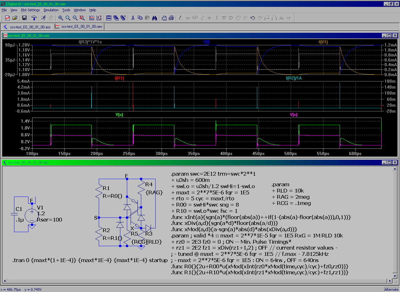
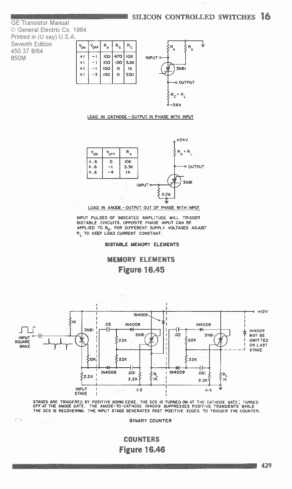
scs test (a variety modified from the 7-th ed. GE Transistor Manual 1964) ::

about :: the following is carried out on intent to find out the low-power-edge function of the scs / pulse-driven logic - - coz there're a lot of old discretes lying around nothing to do with - - in most cases the DTL is out performing such in a sense of power efficiency (but there are few exceptions and some conditional exceptions . . . most yet to be defined . . .)


(-a-) -- incomplete design of low power HOLD capable RAM/Counter . . .


(-b-) -- i guess the proper operational voltage levels' range selection allows the following to operate without pulse amp stages . . .


(-c-) -- ↓it↓ draws about 10mA per cascade/stage for about 400kHz CLK src. (& takes an additional circuitry to read the trigger OUTP levels . . . e.g. adding even more power use in real implementation . . . )


[Eop]

Monday, April 24, 2017

testing the Cool Bit OSC-s for seeming L.e.d.spk. measurement

actually for OSC frequency measurement ... anyway

made a real test with hybrid vid.amp ~ dif.amp circuit but it didn't work reliably enough to be sure of the frequency (so i hope one of the next actually'll 2 the 3-ck before i need to set up some opampsh¡t)

1-st Std. (modified)


2-nd -- an emulated tunnel diode (modified)


update 2017.04.25 :: some opampsh¡t


[Eop]

Friday, November 11, 2016

Shockley Diode , Tunnel diode , SCS SCR - BJT alternates study

Shockley ::

Dev. :


Low Voltage Neon Tube Replacement for ring counter:


Optimizing Hysteresis Curve:


Voltage pass over detector::


the following circuit may be possible to dev. further to a low speed tunnel diode variant:


Shockley to SCR ::


SCR RAM cell:


SCR Binary Counter:


[EoP]

Tuesday, November 1, 2016

Low Voltage SCS Counter Experiment

. . . integrated the www resource (poor) with my past experimental Lo voltage SCS designs . . . to just about get a working theoretical "New One" -- the 2 things marked on a fig. tell us that such is not likely to succeed in practice ...


actually i was playing around with oscillator designs the SCS-s in mind -- the cool feature about this thing (scs) is like some modern GHz MOSFET counters also DRAM e.c. those things can be designed to use practically no current and then shift 'em to another state by a narrow pulse

so, while i achieved my next osc. i studied in parallel an old electronics book - came across with ?? neg. triggered ring counter ?? thought to investigate it , improved the "CLK" shown in book for 1.2V supply . . .


after no success with the counter i actually realized that the TYPE of a counter i'm using for my improved CLK uses the pos. going pulse . . . yo!

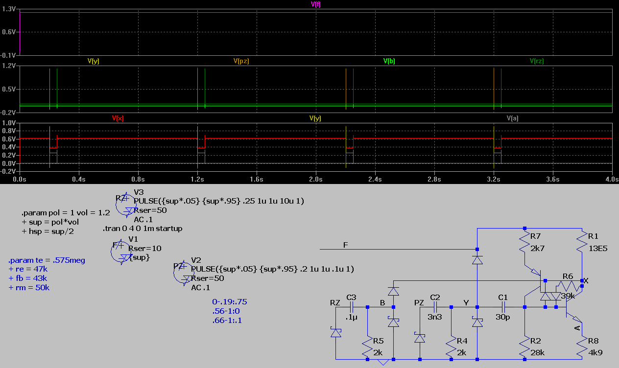
. . . usually i finish what i started so the 1.fig. of this post actually shows the finished 1.2V design

for incase i'd ever need such in practice - i converted it to higher vtg. v. where the SCS is more likely to operate in realistic supply range . . . -- the ▼ "signal forward continuity test" ▼


► what's it made of ▼▼


it's tricky to get the signal out from low power "oscillators" -- here's one possibility :


PS! -- as the simulation in Spice may perform up to 1000x better than the actual circuit in real then it's not recommended to rush blindly building large systems composing them from the unknown / not studied designs
-- it's about 1 to 1k x that averages to ²√(1·1000) = 30dB = apx. 32x in general (more usually it's about 10x - maybe coz i ban the designs that perform worse ...) -- to get this right -- say if your 10Vdc PSU design has a simulation peak error ±24µV then in real device the appropriate value is to be expected ±24mV -- so it's 1000x change in relative error . . . as ±24mV/10V is ±0.24% then the common understanding of 1k x performance drop can't be grasped right without knowing the preceesding

 -- it's also why i don't build much of the stuff -- coz it takes testing separate stages . . . 1 by 1 . . . also verifying similar (same circuit) stages built from real components (with deviating parameters) that usually ends up in narrowing the operating ranges . . . without all possible fancy lab equipment in hand it takes more time than there is available . . .

... e.g. if you find such (SCS counter) interesting you have to perform further development-testing with (/based on) the real components you have in hand for such . . . before attempting to integrate it to any larger application !!!

[Eop]

Thursday, March 24, 2016

Random

some tests ...


an attempt to get this thing to work at 1.2V . . . the lesser the resistances the greater the speed the more narrow the operating range (resistor = current regulator) , the higher the voltage the faster the qircuit the more sensible a decision to buy the commercial stuff (muhahaa) ↑↑


 how to amplitude limit the above the kHz sine wave ↑↑

[Eop]

Wednesday, January 28, 2015

1x versus 2x (AA) powerable SCS switch simulation experiment

the goal was to study a possibility using the SCS bi-stable switch for a memory element (trigger)

it seems the 3.8V is here a critical lower limit below what the implementation of anything gets very difficult -- determining the operating range & conditions
a somewhat complete test : timer : driving pulse former : electrical switces : 1bit RAM : readout buffer -- 1x AA schematic
(an old thing revisited) here the critical voltage is around 1.8V - to drive next switch without pulse amplifier -- 2x AA schematic
and thats it for now -- btw. incase you want to build any of such you need to separately tune/verify. each trigger-stage -- 1-st as an input 1 then as an output one /!\ besides , the set of any number of , may form a closed system (so that adding a stage may require retuning the entire N+1 stages) + trivia -- you also need to verify error free operation under varying supply and specified frequency×duty combinations (and even then you still may expect occasional transition failures for 2x AA v.) -- so if you need a complex app. use commercial "pre-tested" logical circuitry (each variant of witch requires a specific measures to gain an error free operation also ...)

Saturday, November 29, 2014

Re SCS(SCR) Counter

extends the post http://chpsndtch.blogspot.com/2014/11/scs-counter-sw-d-capacitor-led-single.html
probing the switching modes ::
an attempt to extend down the supply range ::
likely an impractical success ::

Monday, November 3, 2014

SCS Counter + SW-d Capacitor Single 1.5V-cell LED Driver

(none of the following is not yet tested in practise - - you have to match the average currents @ critical chains , in case of a failure the grid should be redesigned to lower or higher currents or conceptually redesigned - - there might be some combinations / features - that never work in practice or won't ever work as good as required - that are hard to foresee)

Re-ranging SCS on a different component base ::


"Simple" circuit that suppose to run from single Ag-cell up to AA


[EoF]

Thursday, October 9, 2014

... Let's put some sh­¡t up e.g. the weird science about MEM and SCS/SCR

What's good about the Blogger if you dont blog , ? yes.

(re-)starting with a lot of diodes 1N4148 + 2N3906 , 2N3904
trying 2-def a microbe-hour csc flip-flop
... it's below the lower half of the kHz range
to induce re triggering - takes deviating from std.
about 170 Hz operation (amazingly valid for full possible supply range ???)

teh prev. "defined" crash-ware (oldies)
Bench for a single stage
~ about 30kHz op.-s
. . . . . . . . . i finally get this memory cell working . . . . . . . . . 20kHz write (with ultra cool power draw)
. . . WHAT WAS UPLOADED WAS 2048x1512px133KB(136733bytes)
WHAT YOU ARE LOOKING AT IS
1600x1181px263KB(268929bytes)
??? -- SORRY I GOT IT WRONG AGAIN SO GOOGLE HAD TO "FIX" IT - g.d. perverts - they just can't leave anything untouched . . .
. . . ok, (it's just) yet another totally unnecessary "optimization" by Google ________ come on it's just a few lines to add to your server code (run 1-ce(onece) per img. upload) to tell whether you managed to increase

1-st - the i-net bit traffic on each(every) future page request
2-nd - thus everyone elses' wait time (making i-net slowwer)

 . . .ok that's about how fast we runn off the fossil fuels , but

 ? what i suppose to do ? chk each time if my img.-s're ok ?? and if not
 ? split'em into smaller frames ,
 ? write extra code for each frame
 ? (uploading 4 images (3 extra file headers) instead of 1)
???? delete the "not successful" upload from "blogger album" (takes to wait all blog images to load b4 you can delete any particular 1 OR navigate from 1-st to requred to delete 1) - in "one word" make a day full of job out of what should've taken 2 minutes

why i always have to take a day free to uplaod single image - IT JUST SO ABSURD AS IT IS

 . . . sorry i don't need to purpose my salary to figure out another "virtual task" - i don't get your game to be honest (perhaps you're just stupid or smth. out of my reach)

this is not a ready to use stuff
a snapshots from on going research dev.
it's like @ this Z-up  the grid does THAT
[eof]