Showing posts with label step-up. Show all posts

Thursday, August 30, 2018

YX8018 ~about "guessing the operation"

→NB←! the following has pretty much nothing to do with the actual chip !!! ←
i just matched some known or guessed data into random simulation substitute


from what we can conclude ::
  1. the device operates best at certain fixed supply voltage (there might be one built in to YX8018)
  2. the best efficiency is occurring below the certain output power = you should not replace the inductor to lesser inductance one without making sure :
    a) that there's enough power to drive the inductor (somewhat aided by the 1µF and 5µH caps inductors at the schematic) ,
    b) that the inductor won't be driven into saturation
    ( ↑↑ ← both are primarily indicated by a notable drop in efficiency compared to initial -- however the lesser inductance does, by the idea, give a* higher output power and usually there is some efficiency drop for "trade" to such* )
  3. the onboard inductor in my particular solar lantern has 4Ω series resistance (it might be useful to protect the mosfet from peak power ? from accidental out of cycle re-trigger . . . or provide some voltage regulation for more up to charge battery) , otherwise there's a plenty of room to install a better inductor (such might also cause the over-voltage at the switch drain -- it must be tested out at max input power)


[Eop]

Sunday, May 6, 2018

1.5 to 5 V dc/dc experimental design

the design and the component values are not being optimized -- but rather tuned for sufficient regulation and efficiency


[Eop]

Monday, October 26, 2015

  • inverter test concept
  • 2 types of pulse generators
  • 1W chaos from fixed +5V

--- shortly -- i built an intuitive transformer to test the solar battery charger design . . . then i attempted to figure out how to drive it somewhat reasonably ---- the op.-g range for following is unknown ---- not speaking of special design for hi current high fq. pulse transformers F;X F;X F;X


the pulse generators are required everywhere not only solar-battery inverters ... so i revisited an old concept


. . . and figured out sort of a complementary v. for it
v. (A)

v. (B)


. . . and a chaos generator - though quite efficient by simulation
v. (C)


[EoP]

Thursday, December 18, 2014

1.2V Emergency Light Revisited

i've built several of these bullsh¡t -- the only one that seems to function fine not been taken back appart to spares -- it goes from 1 AAA about 24h , perhaps more , then simultaneously restarts at low battery after being "mute" at some 36h after initial 24+h time of operation , then it works barely visible next 24+h - - i guess (for obvious reasons i haven't just sat and watched what it exactly does) -- the grid :: (R2 here is to match the BC847 to a real KT315 ) the measured operational data :: avg. 1.4415V (40...50 assume) 47mA @ input terminals , avg. 5585mV(28.5...28.7mV @ 10.3Ω res. = ) 2.7767mA @ "High" voltage terminals - gives us apx. 22.3% efficiency in NRG2NRG and 11.2% efficiency in NRG2Light --- the blue light being well detectable gives here the effect of "successful" design (& sh¡t ...)                 ... so revisited v. :: ◄ that thing matches the real "GO" better than the previous simulation -- apx. measured / derived operational data :: 1.472V ~47mA @ input terminals , 8.37V 4.59mA @ "High" voltage terminals - gives us apx. 55.5% efficiency in NRG2NRG and 27.8% efficiency in NRG2Light --- there is no experimental data yet about the responce to an input power variation (just wanted to verify such works)

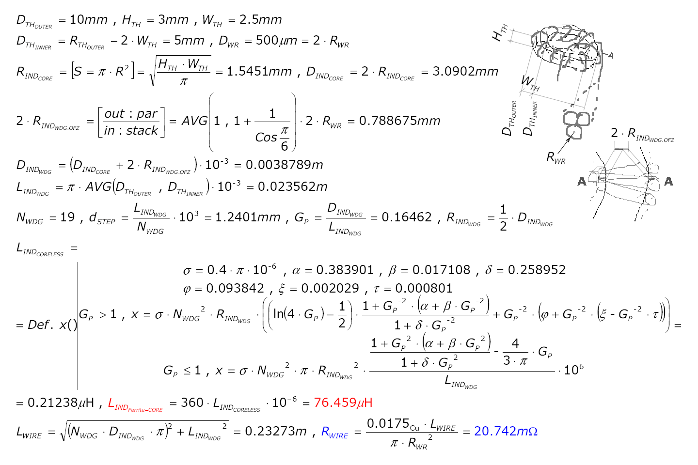
Confirming that the "guess" value used for inductor in the last DC-DC converter does not fall too far from the actual 1 ... ◄ about
xSpiceComputed-!- Error
Inductance60µH76µH68µH ± 12%
Resistance980mΩ*
(39mΩ)
21mΩ30mΩ ± 30%


* -- assumed / defaulted to - diameter 0.1mm* (corrected for 0.5mm)
-!- -- the error is given so because there's no data about the real values (should be derived experimentally)

some changes :: ... usually there's not enough power to push the power transistor ...

(Added 2015-01-10) LTSpice Src ...

[EoF]

Monday, September 8, 2014

1.2V LED driver dev.

it's quite simple to make 24% to 42% efficient 1.2(read 1.46V) "Step-Up"-s or - a less simple - up to 60% efficient (but then low current) 1-s . . . . . . . . . this one promises to be exception to prev. - K-words ::
  • 100µH
  • a "right" frequency & duty cycle
  • special set of transistors
the img. name is misleading relict !

futher to implement ::
  • sw2 & feeding the oscillator from HiVtg. after start up
  • adjusting the cycle according to emptying of the battery
    from (1.46V,250mΩ) dn2 (1V,1Ω)
  • optional blinking mode when battery is too low
  • other

Monday, April 7, 2014

(another) 48h day

staying awake in extended periods shifts your mind to weird states . . .

. . . ? redesigning the capacitor covers ?XD ::


for test-build we don't want to have exposed conductors around << /!\ /!\ /!\ >> otherwise what we just did was generating a heat insulation that in Hi-AC signal env. may cause the un-wanted sudden temp. rise and explosion -- i blew decades ago shortened X-mas lights' active preload - well it stayed in operation 60h and was operating below the max. ~ 250 V allowed marked on caps - i guess they newer tested'em for this particular mode ...
... in other words - as with modern Ni-MH chargers - designing "always-ON" equipment is reasonable to support with /!\ thermal /!\ shutdown relays(/controller)
_______________


about 48 h - prj. :: a long story short it's test-approved forgot and now re test-approved fact that designing a simple boost converter for LE 1.5 V feed performs a lot of WORSE than the SPICE predicts ((there're few exceptions of course ...)) - so, well in common / most cases -

random ::
+

 - the identified issue is BJT-s' base bias -- usually 200 k is "near unity" 4 CE-stg. with 1.2 V feed -- junction charging C-E saturation just occurs too slow - in common 30mA from single battery is most efficient upper limit ::

1.2 V x 30 mA / 12 V = 3 mA >> correcting (best known 74%) >> 2.2mA ??? while the Spice shows boldly 300 mA input and 22 mA output -- while again best practise goes more like 600 mA in and 10 mA e.g. >> 1 7 %   e f f i c i e n c y <<

SUM :: we go C what the fet-s can do -- starting with basics ::


((now i have to build that bullsh¡t -- whitch doesnot mean it's gonna work ...))


[EOP]

Saturday, February 22, 2014

200mW Boost Converter

what we got::
η=69% with the ® transistors (see next fig.) the η'd B around 80%
where we started from::
η=89%
CMOS supply dev. ::
η≤50%
"supply noise" ::
Low ON Resistance N-MOS alternate dev. ::
η=71% it can be greater if the useful load can be set much above the 1.6mA of the CMOS supply

[end of this post]

Sunday, February 2, 2014

30mW Boost Converter

this is just another of the many v. of this circuit
however here we matched the reality to simulation and
then fine tuned the simulation to match the actual circuit


the not shown series resistance for the inductors (114 µH) is apx.  2point16 mΩ

the above circuit showed some 84% conversion efficiency at lesser loads with the ® 2N3904 (not the КТ315Г it's been "converted")

* the bigger the wire diameter the grater the power that can be converted per unit time
* the more turns and (the lesser the wire diameter (the grater the series resistance)) -
 ˙ the lesser the start up voltage but also the lower the power per unit time

so if you need energy efficient microbe hour :p converter use the lower options (powered by cell button batteries)

although you may make a way (!!) more complex circuit with higher options - that runs occasionally from (!! then required) high energy source or from low energy source loaded capacity (!! requires specific "controller") to maintain the overhead for the application power regulator (!! another addition)

the capacitor in parallel to LR6 should be lesser for greater operation frequencies such as the following 40MHz circuit (not fully explored nor built)

it may become unstable from unpredicted modifications nor can i say if it has anything to do with reality

[EOF]