Showing posts with label Linear regulator. Show all posts

Thursday, March 14, 2019

Progressive current limiting

Figures ::


Legend :: opamp.Q1 mirrors the current at R5 , opamp.Q2 limits the current progressively ... and incase of the SC it cuts the output the more off the lower is the output voltage -- so there's double level progressive limiting (the fig.2 shows the 1-st and the fig.-s 3 to 5 show the 2-nd - a short circuit - limiting levels) . . . the resistor values for R24 to R26 and R21 , R22 , also for the R14 may need to be adjusted to get the real build of the circuit stable (maybe it takes more adjustments -- but these are known to be more likely critical at this stage of dev.)

[Eop]

Saturday, October 6, 2018

revised the yy78Lxx 5V variants

tests so far ::
PS! -- although the following setups perform well the real tings may not coz the Spice models use highly accurate fixed current sources - - - while there's no indication the real 78Lxx-s had any implemented //// the last time i tested my real 78Lxx-s showed an ulta poor performance where the voltage started to drop already at !!!above 30-/40 mA drain and significantly differed from the nominal at 50mA (while i didn't notice them getting hot -- so that a possible thermal prot. feature could have had engaged ???)


partial apx. match to d/s ::


[Eop]

Monday, March 19, 2018

testing out the custom xx78L05xxx variant

amazingly -- worked from scratch -- no matter the blind guessed j-Fet and Zener values and much randomly chosen 2N2222 and 2N2907 for "tech."

but the OUTP voltage little drifts with INP voltage and the fold-back (from140mA) starts to work from 14V external supply ( ? wrong zeners . . . )

the model is currently adjusted to 5.0V at Abs.Max 35.0V input

as usual the component level model (78L05) is more stable than the .cir net-list model ( LT1761-5 )


NB! Not all the plotted parameters are relevant/consistent with the ↑↑ shown test
(they are relics from another grid that was used as a draft for these ones)

"Level 2" ::

. . . with custom LM324 CLM ( Component Level Model ) (( which i also needed to test ))


This is why the net-list models are not good at complex circuits ↓↓ (i actually didn't expect to get it "stable" . . .)


[Eop]

Tuesday, October 17, 2017

LM317 component level versus LT317 macro model

about the real things LM317x LT317x

simulation models (Custom against Linear)


a curious thing ↑here↑ is that the CLM(component level model) seems to be more stable than the ↓next↓ macro (more simplified) model


Models about ::


[Eop]

Tuesday, March 14, 2017

Linear v. Switcing regulator - a specific occasion

Amazingly the case when there's no much difference
(that was revealed in revising an old design . . . )
-- the input supply is some avg. rectified output of a wall transformer


[Eop]

Thursday, January 19, 2017

3-transistor "precision" LDO

Left-Below is the ® , Below-Right is over current-(/SC-) proof advance of it (as usual -- not tested as a real thing !)


[Eop]

Friday, November 11, 2016

yet another 1.2V supply

Dif. Amp. Draft design:


Dif. Amp. to Op. Amp. - with overshoot shunt:


New concept with a short circuit limit and indication:


[EoP]

Saturday, July 9, 2016

rev. +1.2V Linear Voltage Regulator with Current Limit

not built in real yet /!\ e.g. possibly no reverse pol. prot. + unknown amount of spec. not handled states ...

[Eof]

Thursday, October 15, 2015

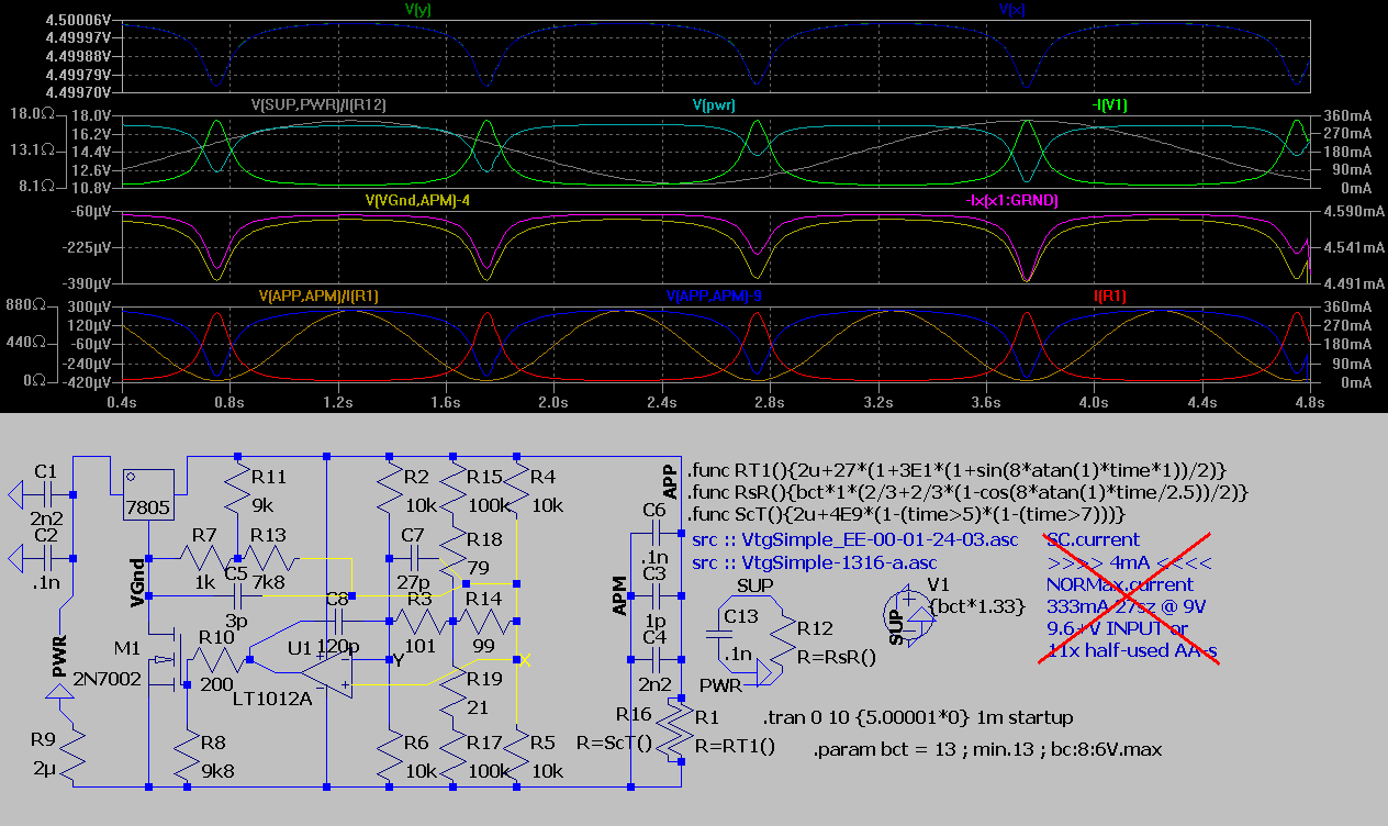
fuzzy science of extending the range of 3-terminal (fixed) voltage regulator

Bew , here we go  . . .
  • in case of ringing inc C2 then C6 then (C8,C7)
  • R10 , C8 (, R8) -- lobe ass filter
  • R11 , R7 -- Vtg. Div.-r
  • R13 , (R3 , R14) -- Regulation logic
  • (R15 , R17) , (R18 , R19) -- fine tune level shift (enabled by R3 ≠ R14)
  • /!\ There is no SC protection (use fuse or you'll loose your device) /!\
. . . it seems the "std." v. of the above has the same error of apx. ±400µV ---- so i added a secondary error correction

the remaining op amp from ´1366/-7 can be used in a separate supply for opamps or electrical-fuse for short circuit , e.c.

[EoP]

Wednesday, October 14, 2015

a Collector load (sc proof) Vtg. Regulator

since the component countfor this bullsh¡t


is higher and it has an error to the range
 of the following (! not built / tested -- but i guess it's not far from it´s actual)


then i guess i gonna get this 1 PCB-d and cased in with an appropriate ( 300+mA @ 10V DC ) transformer , damn it takes long to test out what you actually need and that actually works as designed -- should've brought a random 600÷1000mA 9V SC proof linear reg. such as KA7809

Update !


now more precise v. of the above is available


[EoP]

Tuesday, September 29, 2015

How to kill your LDO

extends http://chpsndtch.blogspot.com.ee/2015/05/two-random-voltage-regulators-practical.html , http://chpsndtch.blogspot.com.ee/2015/04/regulator-redesign-lab-as-always.html

Getting some numbers . . .
a quick fix + improved zener
(*update :: i used in practice a darlington - not the super ß - "power switch" - this cfg. seems to have a better supply-/load rejection than below ↓↓)

insane . . . improving Vs rejection + "digital" current limit


"back to analog" -- adding batteries . . .
 (*update :: see above ↑↑)

(hope idon't uploadthis2wce) -- a fold-back sc current Lim.
[EoP]

Friday, May 22, 2015

Two random voltage regulators (practical)

a pre-conditioner (the 1-st of 2) for 9V linear reg. amazingly falls to that 10% of circuits that GO as they simulate !


an error-trial fast compile of the 9V from 12.8V - even more amazingly the circuit falls to that 2% of circuits that actually GO better than they simulate -- this 1 has 2...3mV output change on load variation -- donno what happens if we vary the input . . . likely the bias increases decreases along the V.in resulting unspec. change for V.out . . . not tested -- the russian KT815 mounted on about (both sides tot.) 1²' (1side tot.) ½²' heatsink (that seems to be sufficient for <avg.100mA <peak.240mA I.out)

[EoP]

Friday, April 17, 2015

Regulator Redesign (/Lab -- as always . . .)

________________________________________________
2015-04-15 ::
¯¯¯¯¯¯¯¯¯¯¯¯¯¯¯¯¯¯¯¯¯¯¯¯¯¯¯¯¯¯¯¯¯¯¯¯¯¯¯¯¯¯¯¯¯¯¯¯
 . . . trying to "de(/un)-bug" the last design from prev. post -- normalize power range , minimize the error . . .

+ a modified v.'s foldback diagram


Customizing/"improving" the 78Lxx for 1.2V

i only guess it's 3.0V
________________________________________________
2015-04-16 ::
¯¯¯¯¯¯¯¯¯¯¯¯¯¯¯¯¯¯¯¯¯¯¯¯¯¯¯¯¯¯¯¯¯¯¯¯¯¯¯¯¯¯¯¯¯¯¯¯
"Minimizing Compile" , exploring the switcher mode v. , experimenting with foldback . . .

thought to use the LT's µ-P 2.5V LDO -- but the 3uA is likely causing it's instability in high loads env.


________________________________________________
2015-04-17 ::
¯¯¯¯¯¯¯¯¯¯¯¯¯¯¯¯¯¯¯¯¯¯¯¯¯¯¯¯¯¯¯¯¯¯¯¯¯¯¯¯¯¯¯¯¯¯¯¯
Optimizing "Design"

Update! :: the foldback re-visited . . .
Update+ :: ±10µV version ::
Update+ :: ±12µV version with foldback updated to support high load capacities (no frequency test - what so ever- carried out + i donno how to thermal compensate - /!\ so i never do /!\) e.g. you have to recalculate the design before any attempt to assemble it

________________________________________________
[EoP]
¯¯¯¯¯¯¯¯¯¯¯¯¯¯¯¯¯¯¯¯¯¯¯¯¯¯¯¯¯¯¯¯¯¯¯¯¯¯¯¯¯¯¯¯¯¯¯¯