Showing posts with label 6F22. Show all posts

Thursday, March 14, 2019

Progressive current limiting

Figures ::


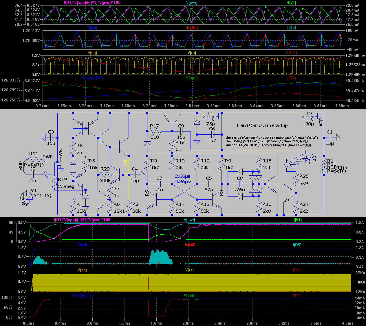
Legend :: opamp.Q1 mirrors the current at R5 , opamp.Q2 limits the current progressively ... and incase of the SC it cuts the output the more off the lower is the output voltage -- so there's double level progressive limiting (the fig.2 shows the 1-st and the fig.-s 3 to 5 show the 2-nd - a short circuit - limiting levels) . . . the resistor values for R24 to R26 and R21 , R22 , also for the R14 may need to be adjusted to get the real build of the circuit stable (maybe it takes more adjustments -- but these are known to be more likely critical at this stage of dev.)

[Eop]

Friday, October 26, 2018

9V-to-5V Step-down concep design

the thing


switching wave-forms at max.-min. load


[Eop]

Tuesday, April 25, 2017

about 6F22

i was wasting some half a day to find out the max. safe discharge current rate for carbon zinc type
there was no such data avail.
-- so i had to make a best guess about

a fuzzy logic follows ::


it is statistical nonsense but since i had no other data avail than GP-s datasheet then what it seems / was assumed is that the average drain over longer time is somewhat constant . . .

. . . so if you want to design an application that uses 9V C-Zn battery then something optimal value is 12mA or below -- that is -- if it is to work 24/7

( it is amazing that we don't have that value available -- if you overload the battery it gonna heat up that first boosts the chemical reaction but likely roughly over 40°C (104°F) it starts to damage internal chemistry further on there might be acid or alkaline leak or explosion or even fire when Li-ion gets in contact with oxygen -- so all such totally insignificant stuff no one needs to know exactly -- especially the EE app. designers )


[Eop]

Sunday, January 22, 2017

5V regulator variants for 6F22

LDO utilizing a low R.DS of a MOSFET


a switchng variant of the prev. LDO !! no current limiting nor other specific situation handling !!

( !note : of course the OUTP loading is inverse proportional to R.int.BATT )

Component count optimized v. of EF regulator


Max. precision v. of prev.


-- the fold-back v.


[Eop]

Friday, July 17, 2015

Design Concept for 9►5V "PWM"

Quick tests :: both are using random interpreted 1.2V oscillators that may not perform so good in practise at that voltage -- the 5V adjusting network is poor , minimal - i primarily needed the P.OUT capability . . .

A) ?? 230kHz


B) -- designed 1-st re-adjusted later 40kHz

[EoP]