Showing posts with label switching regulator. Show all posts

Monday, January 14, 2019

regulated switched LED regulator designs (experimental)

the thing ::


how to set it up in practice . . . involves a number of tests ::

  1. Detach the mosfet and the feedback Mod line -- from simulation and from build
    Regulate the frequency and duty to match those of the simulation
  2. Re-attach the mosfet , ( /!\ /!\ /!\ ) set some 20Ω or greater in series with the 6LF22 to limit the current through LED-s --and-- set electrical fuse or limitting resistor in series with the LED-s --or-- double the number of LED-s ( /!\ /!\ /!\ ) - - - - - - - - - we are going to verify the transformer ::
    do the same mods on the simulation and test for the differences . . .
    -- if the real build performs worse you need to recalculate and rebuild the transformer accounting for resistance not present in ↑this↑ circuit
    -- if the build performs better then the primary side is "over-driven" the timing of the switching wave-forms has to be re-evaluated and adjusted
  3. Attach the Mod line --and-- ( /!\ /!\ /!\ ) set the regulation to be greater than in simulation (!! dont remove electrical fuse or extra LED-s !!) ( /!\ /!\ /!\ ) ,
    -- regulate it bit below the desired LED current (in case the regulation failure -- the regulator has to be re-designed --or-- replaced with better known one)
  4. if everything worked out so far the additional tests are required such as ::
    • test for bit higher than simulated input voltage (the Cl batteries may have up to 1.8V per cell e.g. 10.8V for fresh 6LF22)
    • test for battery contact strobe !!!
      -- here everything can fail -- use fuses and perhaps build a protective controller that can fast switch off the circuit under test
    • test for the lower than in simulation input voltage !!!
      -- may result in oscillations failure and the MOS-FET being "constantly ON" (attempting to remain in conduction mode) . . .
    • etc. ...

Basic simple ::


add VCO , Mod2 divider , the 2 to 4 decoder and a current sense / +integrator -- and it's basically done . ..


[Eop]

Saturday, January 5, 2019

incomplete (non-regulated) switched LED regulator designs

emerged in response to a latest local blackout event + a realization that the 77% of the energy would go "smoking in to the air" on the current limiting resistor e.g. the light would be ON some 3.3x less than otherwise . . . (but in the case of no (any) light even ←that would do ...)

1-st ) -- the step-down¹ with the separate regulation of voltage and current -- a case study ::


  • ↑ yields the 39% (and worse ...) efficiency for given setup ↑
  • ↓ has an unwanted startup overload spike ↓
    (might be removed by delaying/modifying the 555 startup)


2-nd ) -- the step-down² using the proven (Hi-Power) switcher variant (@ Lo-Power) -- gives a slight step in efficiency  but requires adding the output load or redesigning controls (such as using the lower power mos-Fet or Bjt ) --and/or-- adjusting the inductor ~ switching-frequency -- to get the efficiency higher


3-rd ) -- the step-up.. (← in my experience has statistically shown to have greater efficiency than the step-down conversion) ..using a commercial switching controller -- has a most promising(/preferred) result here . . . considering i didn't spent much time on fine tuning the following setup -- it does however have an unwanted startup over-spike (that may damage the LED-s on a "wrong day" or in case of too frequent power cycling)


SUM ) -- two last variants compared


PS ! ) -- as the title says -- !!! all these designs are functionally incomplete !!! -- e.g. :: not set to handle various specific situations , such as : too high input , too low input , output short , reverse polarity , switch/inductor failure ,  etc. ...

+Plus ) -- Couple of things to compare the prev. against . . .

1 ) -- an experimental converter (is lacking the control module -or- a concept for)


2 ) -- basic , simple -- linear regulator


3 ) -- basic , simple -- Op-Amp v. PNP versus NPN input stage


4 ) -- basic , simple -- Op-Amp v. PNP input stage (target LM324 or other Quadruple Op-Amp)


5 ) -- basic , simple -- linear regulator (for target input of 8x AAA to aged or not full 7A·h 12V PbSO₄)


[Eop]

Friday, October 26, 2018

9V-to-5V Step-down concep design

the thing


switching wave-forms at max.-min. load


[Eop]

Wednesday, May 2, 2018

555-s based SMPS test

as is ...


... in practice it requires a sharper or more discrete response for larger errors -- this one could do for relatively steady load -- a bad point here is that increasing the controls' sophistication impacts either on efficiency at light loads - - - or retail tech. such as in SMPS controllers where the dev. of such is expensive and won't pay off for prototype solutions . . .


+ an update to the schematic in the prev. post


no pwm just switching test
*

[Eop]

Monday, January 8, 2018

Regulated single 1.5V AA Led Flaser Concept


there are different 2N3904 models the ones with 100mA I.F and the ones with 150mA I.F -- in REAL implementation of this circuit you may need to multiple parallel these for a switching transistor or use a more powerful low U.CE type one


PS! this is a simulation experiment - the real circuit and components for a similar output parameters may somewhat or significantly differ of those shown in the fig. !!!

about & how we got ↑there↑ ::

initial circuit
the op amp regulation promises worse results than the transistor regulation on the first figure

[Eop]

Tuesday, March 14, 2017

Linear v. Switcing regulator - a specific occasion

Amazingly the case when there's no much difference
(that was revealed in revising an old design . . . )
-- the input supply is some avg. rectified output of a wall transformer


[Eop]

Tuesday, December 6, 2016

Old Op Amp test PPM dcVC check

5V operation of LM358


pulse position modulated direct current switching voltage converter QC

! likely source® http://www.24vpower.com/dianlutu/89.html
converting it to 20V to 5V variant


. . . adjusting switch turnoff time ... down to about ~ 100ns


no further checks (e.g. output short circuit , load steps , starting at mild overload ... )


[Eop]

Tuesday, November 22, 2016

concept design of the switching dc voltage inverter

it seems the fast comparators are the soul of the whole thing - replaced the fast op amps coz they failed at various cases


uses 2N3906 2N3904 2N7002 BSS84 - not especially optimized or tuned for anything specific - no real life testing ... !
[Eop]

Friday, July 17, 2015

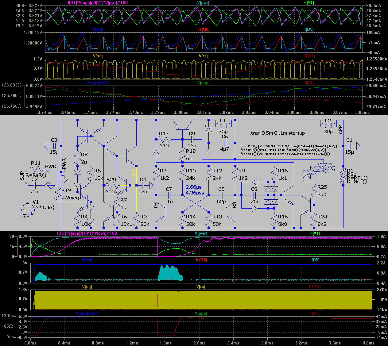
Design Concept for 9►5V "PWM"

Quick tests :: both are using random interpreted 1.2V oscillators that may not perform so good in practise at that voltage -- the 5V adjusting network is poor , minimal - i primarily needed the P.OUT capability . . .

A) ?? 230kHz


B) -- designed 1-st re-adjusted later 40kHz

[EoP]

Sunday, April 5, 2015

Adjusting the adjustable voltage regulator

The goal as in trivia is to gain more stability and precision while keeping the design robust . . .


9V ± 1.8µV , 300/646mA (max.load/SC.supply current)
-- the stability (ringing(OpAmp-s e.c.)) + SC condition are a question marks here


((Simple with SC don't care /!\)) 9V + 0.6 ± 2.6mV , 300/687mA


((Simple SIPMOS with SC handling)) 9V + 4 ± 475 µV , 300/687mA


((BJT alternate of the above)) 9V - 48 ± 255.6µV , 300/56.7(398)mA (max.load/SC.supply current.average(.peak))


((feature test for FET switching)) 9V - 7 ± 13mV , 346/706(CuLm+)mA , 23.7kHz (here for err. compare)
-- the main targets were the inductor&frequency versus load&error (the current limit is a quick fit -- feature test)

[EoP] (XT kogu aeg on mingi vitustus selle küljendamisega -- ma korjan mittevajalikud reavahed maha - aga voila! - peale save´imist on nad kuskilt tagasi tekkinud (teksti ja pildi vahele topitakse <BR> tag´id - et kui on huvi lõpmatuseni oma tekstiga jantida ÕööÖרÛÜÚÝ♒☣☠☦☯ ))

Saturday, January 10, 2015

Random Voltage Regulator Tests

Random keywords : stability, efficiency, ripple, startup time, slew rate, deviation :::


(Added 2015-01-10) LTSpice Src ...

[Eof]