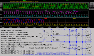
the idea as usual for 1.2V (single battery fed) logic is to make it work at all discharge levels of the battery (1.68V) 1.46V . . . 1.1V(0.75V) -- in common after the battery is discharged below 1.13V it´s power output is limited 4mA continuous drain (10 to 20mA peak loads) and it´s getting worse in minutes - for rechargeable Ni-MH-s the critical voltage is likely lower - that is - they preserve their power output below 1V (unloaded) terminal voltages
the 1-st run ::
Correction: to drop X0 faster usually takes to decrease RC and/or to increase RB
and the 2-nd run ::
it has 760mV zener that means the supply should be above that level
the question here might be that why to go so complex when the 2-transistor 2-resistor + number of inputs count of diodes do the trick as well . . .
. . . it is that - due the differences in real components - the signal continuity may be lost using simple design
+ the above designs "eat" better the supply and input signal range variations - making it more realistic that i might do something with old SMD transistors "saved" from old blown devices . . .
[Eop]


