Blind tuned to work with some consequences from . . . at 5V v. of it . . .
-- with the single BJT stages and the battery feed and "sensitive"(tuned) oscillators -- it is most unlikely to get anything "properly" to work -- . . . -- moreover with the 1.2 volt battery the grid has to be tuned to work in 3 different areas of operation of the bipolar transistor -- low-voltage (below normal) , normal voltage (for BE CE voltage drops) and hi-voltage (above normal) -- that has to be achieved with fixed biasing elements -- . . . -- in below circuit the critical elements appeared to be C1 , C8 , C4 , C10 -- less C1 more C8 ... also the series connection of C4 and C10 = Cp of the X-tal resonator it first started to "charge" the X-tal with ratio 1.2x : 6x Cp but as i increased C8 the opt. ratio changed to 1.5x : 3x Cp ???

the "above normal" range ↓↓ -- i just fast tuned it just to "charge" the X-tal -- this to see if the current waveform for X-tal goes "trapezoidal" (← failure in a sense of frequency stability -- i assume) or stays Sine . . . . . . . . . well it stayed sine -- but for this one the further frequency tuning and likely some attenuation is a must ↓↓↓↓ (see next) . . .
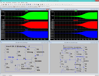
there is a very simple circuit for 8MHz crystal but (it requires less energy for startup) and it also works only with very narrow range of the supply parameters -- so -- it can't be simply adapted for 32k
. . . ?amazingly i've already proven it otherwise ???
8MHz ::
the C14 caused pulsation is likely causing and the instability in the 5v experiment above ↑↑↑↑
32kHz ::
Low NRG 32k ::
Ultra-tuned UHF ::
nearest match from web
http://www.nutsvolts.com/magazine/article/bipolar_transistor_cookbook_part_5
The failed but extremely fast starting UHF resonator Osc. experiment
[Eop]


