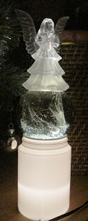
Theres 2 figures in series connection (2x LED-s -- 1 per figure) -- since the least energy gets lost that way -- here what got implemented :
the next i found too complex to build for this simple task (where actually a properly chosen resistor would do fine . . .) -- but i wanted to check the circuit in action (which i rarely do) -- so the above v.1 worked fine with no modifications required (with 1Ω resistor as originally designed for 14mA actually drawing 10mA -- no much difference -- the dimmer might be and better as it won´t "jump into your eye")
... the creep itself ... in action XD ...
. . . the crystal balls´re not from the original set . . .
i actually researched the cc design-line further for Op Amps as i attempted to control 555 charging cycle as shown below . . .
. . . and the best results (for misc. cc - sink) gave the next weird setup (no good for PWM or pulsed setup)
unusual use of 555 timer in phase shift osc. setup . . . the modulation input - has no desired effect here - coz lowering the upper trigger level dis-balances the charging currents that'd need to be cc sourced - but for 500kHz i didn't wanted to extend the test for here . . .
update 2016-12-21 14:38 UTC+2h (-2h UTC) ::
opti´ng the timer out of the circuit ???
? there seems to be no lower limit but the capacitors´ manufactured and what you can afford
[Eop]


No comments:
Post a Comment