such as -- adding some transparency, new background & some free fall zone to the end
((looks i didn't crash my blog yet - iik))
Friday, January 31, 2014
Thursday, January 30, 2014
Custom Simple Linear Regulator
... built and tested but not fully
~._~ i'm not going for a contest - so itsabit trashy look
[EOP]
here's the stuff ::
~._~ i'm not going for a contest - so itsabit trashy look
developed from ::
[EOP]
Friday, January 24, 2014
about AA or LR6
i used to believe that the battery capacity is not been near entirely used (by random application) so i a bit "wasted my time" on studding 'em // -- as in fact it turns out the battery keeps it's output "Up" for up to 90% of it's capacity
the processes present at exploitation (not discussed further in this article - just listed)::
0) internal electro mechanics and electrical field set up by load current and env. temperature
1) reduction of the chemistry induced charge
2) chemistry change by discharge
3) re-inducing the charge by present chemistry
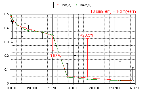
i made the series of simple discharge v. time tests
the values for internal resistance and electro-motoric force are derived theoretically(1)
notice! that the experiment recorded just terminal voltage and current levels -- everything else is derived
the legend explained::
C836mAh(%) -- the percentage of "full capacity" -- 836mAh in this case
iC -- 1 (100%) minus C836mAh(%)
E -- electro-motoric force in volts
r20Ω(%) -- internal resistance / 20Ω
Iest(A) -- estimated terminal current in amperes
P(W) --U x I -- external- / diffusing power
Csimple(%) -- R.const C battery alternate (as using capacitor + delimiting resistor inplace of an alkaline)
about the error of the used theoretical model(1)
i speculate that the master fluctuations are due error in device redings -- whatever the case it's not so significant
the E(r) or r(E) dependency(1) is defined from measuring multiple AA cells at their various discharge levels
notice! that there's no time dependency defined
[EOF]
Non real world Constant current sources Comparison
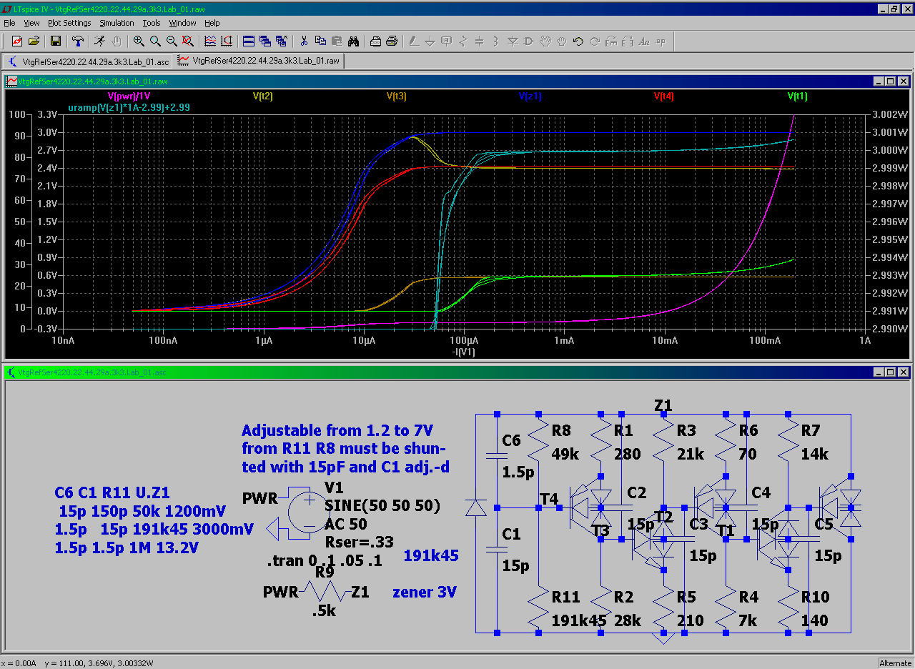
NB! :: the brought circuits are not tested in reality -- they only represent a technical hint to a "What such grids may behave like" -- they are modifications from std. current source cirquits
the long story short -- THE TEST ::
here's no intentional temperature compensation = in real there is likely a significant difference to these plots
note:: the last shown (the lowermost fig. , right) is actually been built but tested near-around-below of it's 5V range (not entirely) -- however it worked better after replacing the HiFq-LoPwr transistors of the shown "zener" with MedLoFq-LoPwr 1-s (that is lowering the "starting point" of a zener - with expense of it's precision x (overall) range loss) -- which however improved the current source in low voltage range
by that i reworked my "zener" concept - finding the following being (/!\) most likely the best (/!\) to use
however this one has a "startup ramp" ...
... i won't show here the "zeners" without "startup ramp" -- coz the're not tested in real
NB! this "zener" HAS a "startup ramp" (remove the capacitors -- and it nastily shows out)
Wednesday, January 15, 2014
How to parametrisize the existing transformer for LTSpice (Simple approach)
What we can simply measure::
1. R1 -- the resistance of the primary winding L1
2. R2 -- the resistance of the 2-ndary winding L2
3. U1 -- the voltage on input terminals (of the winding L1 the same as R1)
4. U2 -- the voltage on output terminals (of the winding L2(R2))
5. I1 -- the current through L1
What we can compute is::
6. I2 -- the current through L2 the I2 = IRTEST = U2 / RTEST
7. the inductance of the winding L1 is derived from::
Z1 = U1 / I1 = ²√(X1² + R1²) , where Z1 is impedance of L1 , X1 is XL1
thus X1 = ²√(Z1² - R1²)
and L1 = X1 / (2·Pi·f) , where Pi = Arg(-1) , f = grid's frequency (50Hz/60Hz)
8. the inductance of the winding L2 is derived from::
η · P1 = P2 or η · U1² / Z1 = U2² / Z2 , where η is transformer's efficiency
so Z2 = 1 / η · Z1 · (U2 / U1)² we don't know the η so we assume η = 1
when we measured U2 we can compute the L2 's value as we did for the L1
What we can't estimate is::
9. η = ?::
by running the simulation in 'Spice that reproduces the experiment shown on the
above figure (assuming a set of RTEST -s was used) we can statistically find the
best (statistically least erroneous) RTEST instances and (by these) re-tune the
L2 value for simulation
so the actual η = P2 / P1 or η = (U2 / U1)² · (Z1 / Z2) but we don'no' it unless we
measure the L2 value in real
NB! as the title suggest we get the L2's value fo 'Spice simulation.
The value for real-life η (for that transformer) is not found nor used --- why?
B-coz simulating with η = 1 ** is tremendously faster and less prone to
"Timestep too small" errors.
(((( i hope the 'bove article is readable ))))
note !
there are four x2 conceptually different L2 values
L2 -- generic (not strictly specified)
L2 -- computable by measured U2 value
L2 -- the real life value (it's difficult to measure it with decent precision)
L2 -- the value derived from re-produced 'Spice experiment
x2 -- the L is the name of the winding(coil) also the name of the variable
for it's inductance -- so in 1-st case the L.index points to L.L.index and R.L.index
in 2-nd case the L.index is L.L.index while R.index is assumed to be R.L.index
(clear as soapy water)
[End of the TEST post]
here's how to apply:: ((((~)%/~=)(&%="~)(&%"~=)?&%" V^^^V chchchch - ok it works now))))
update 16 jan MMXIV 7:13


