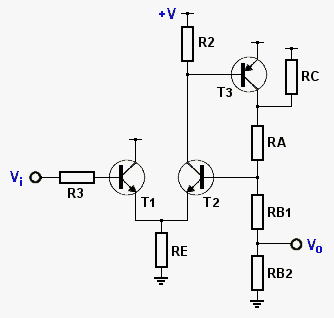
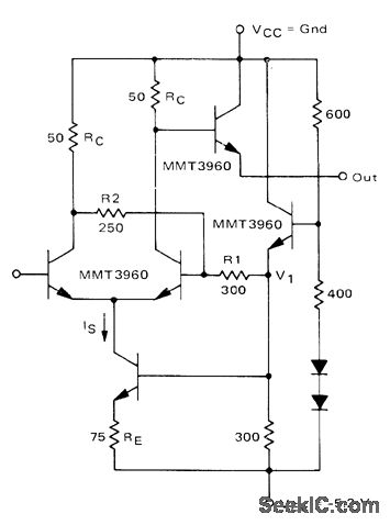
the following circuit is actually an incomplete design halted in the middle ,
surprisingly it appears to work as is in a quite wide supply range ???
this is the latest 1.2V v.
PS! -- what makes it exhaustively tedious to make any sense for unregulated or non-pre-conditioned single battery operation are the BE CE voltage drops
e.g. the normal operating range for Si-BJT-s starts from somewhere at
( 1.2V !!! ... 1.26V ... 1.53V ... ) more likely above 1.86V
- actually it's combining 3 different oprating ranges and optimizing these with 3 extra limitations
► <1.1V , 1.1 to 1.53...1.86V , above 1.53...1.86V
► + adding to this -- optimize the number of components (budget)
► ++ adding to this -- optimize the power (budget)
► +++ adding to this -- maximize the frequency bandwith (capable from static DC to HF operation)
near static I/O correspondence at operation from 1.2V supply
[Eof]
Wednesday, March 22, 2017
Saturday, March 18, 2017
Insane
Couldn't figure out non ~AC use for j-Fet ... bullsh¡t -- the DC setup for j-Fet at 5V supply allows it to be used as a 1-st high impedance stage at 4-stg voltage amplifier which is likely frequency dependent thus non-DC amp
so i combined what i had seen in web with what i'd learn so far . . . and we got a nice median of previous post
(whats it worth ´>.<`)
[End of this bullsh¡t]
so i combined what i had seen in web with what i'd learn so far . . . and we got a nice median of previous post
[End of this bullsh¡t]
Friday, March 17, 2017
Verifying some web Schmitt trigers
1-st i attempted to make sense of
this beast (src.) . . . is the T3 right polarity? coz i couldn't get this thing to generate any useful output that way ... anyway there's what it end up :
and it's damn slow for dif. input stage -- where the good point is it's having a high impedance input
2-nd we got something called CURRENT-MODE SCHMITT TRIGGER
or PULSE_COMPLETING_SCHMITT
if it's an OE output -- then here some more realistic boundary for it :
it appears fast and even faster - but input seems to be very low impedance???
next i should try some j-Fet 1-s ...
[Eop]
Tuesday, March 14, 2017
Verifying some Web Circuits
just curious . . .
src:: http://www.eleccircuit.com/the-cmos-current-controlled-oscillator-circuits-cco/
i couldn't get it work as shown there ??!
(this simulation uses component level 4069's model)
verifying a light bulb
? 18µA F;Y -- is the magic word Tungsten
[Eop]
i couldn't get it work as shown there ??!
verifying a light bulb
? 18µA F;Y -- is the magic word Tungsten
Linear v. Switcing regulator - a specific occasion
Amazingly the case when there's no much difference
(that was revealed in revising an old design . . . )
-- the input supply is some avg. rectified output of a wall transformer
[Eop]
(that was revealed in revising an old design . . . )
-- the input supply is some avg. rectified output of a wall transformer
[Eop]
Saturday, March 4, 2017
50Hz VFD filament drive test
applies to the 16ohm cold filament cathode (i don't have the warm data yet) just the beginnings
an attempt to decide whether to use sine or square-wave drive
- though the overall efficiency for this circuit is below 10% - then right now i keep preferring it
- simply coz setting up a consistent pulse drive is a way more complex (unless you have a separate supply to drive the pulse TF from)
- still the peculiarity of the desired output (center tapped winding) sets extra requirements to this drive (you actually can't drive it from the single switch reliably for balanced output or then making it reliable seems at this point more complex ((error prone in practice)) than using a sine-wave drive)
anyway what we got
PS! reproducing the TF in practice is not so straight forward coz of speculative winding resistances
(winding resistances usually are orders of magnitude lower than the corresponding impedances - so we likely shouldn't care) but here the R.primary much affects a lot of "operationals" that have to fit !optimally&practically for 6LR61 - this in turn requires to redesign the secondary winding -- is quite lengthy error trial chain + in addition to confirm/re adjust in practice (possibly start the design over and over again . . . !!!)
+ did some quick static measurements on . . .
if you increase the AN GT voltages the filament feed may be lesser but there seems to be a threshold A-G voltage and filament power starting from where the fade left/-right is reduced and the seeming symbol brightness does not much increase
also - when i experimentally found the FUTABA's operating parameters i didn't expected so high filament current so i had to reduce a lot the gate/-anode voltages to get their apx. min./-normal values -- what was studied is that while the anodes did glow most bright at AN set to 27÷36 V (gate same or 9V less) then going up from there they seemed to start dimming again ?? !!!
[Eop]
an attempt to decide whether to use sine or square-wave drive
- though the overall efficiency for this circuit is below 10% - then right now i keep preferring it
- simply coz setting up a consistent pulse drive is a way more complex (unless you have a separate supply to drive the pulse TF from)
- still the peculiarity of the desired output (center tapped winding) sets extra requirements to this drive (you actually can't drive it from the single switch reliably for balanced output or then making it reliable seems at this point more complex ((error prone in practice)) than using a sine-wave drive)
anyway what we got
PS! reproducing the TF in practice is not so straight forward coz of speculative winding resistances
(winding resistances usually are orders of magnitude lower than the corresponding impedances - so we likely shouldn't care) but here the R.primary much affects a lot of "operationals" that have to fit !optimally&practically for 6LR61 - this in turn requires to redesign the secondary winding -- is quite lengthy error trial chain + in addition to confirm/re adjust in practice (possibly start the design over and over again . . . !!!)
+ did some quick static measurements on . . .
| Name | ИВ-28А | 7-BT-295GNK |
| image | ||
| Gate voltage | +9V | +9V & *more |
| Anode voltage | +18V | 2× +9V & *more |
| Filament current DC-driven to neg. from GND | 25÷28mA | 52÷62mA |
| Anode brightness adjustment ► increase voltage for edge segments ◄ | not required for parameter values shown above | required by unknown factor ► required less for gate , anode voltages *exceeding the ones shown above |
if you increase the AN GT voltages the filament feed may be lesser but there seems to be a threshold A-G voltage and filament power starting from where the fade left/-right is reduced and the seeming symbol brightness does not much increase
also - when i experimentally found the FUTABA's operating parameters i didn't expected so high filament current so i had to reduce a lot the gate/-anode voltages to get their apx. min./-normal values -- what was studied is that while the anodes did glow most bright at AN set to 27÷36 V (gate same or 9V less) then going up from there they seemed to start dimming again ?? !!!
[Eop]


