1-st i attempted to make sense of
this beast (src.) . . . is the T3 right polarity? coz i couldn't get this thing to generate any useful output that way ... anyway there's what it end up :
and it's damn slow for dif. input stage -- where the good point is it's having a high impedance input
2-nd we got something called CURRENT-MODE SCHMITT TRIGGER
or PULSE_COMPLETING_SCHMITT
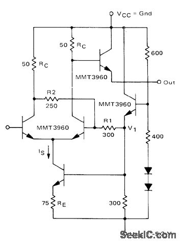
if it's an OE output -- then here some more realistic boundary for it :
it appears fast and even faster - but input seems to be very low impedance???
next i should try some j-Fet 1-s ...
[Eop]
Showing posts with label schmitt's trigger. Show all posts
Friday, March 17, 2017
Wednesday, August 5, 2015
custom 1.2V logic "ser.-s" revised
what was revised ::
(( not too very good as seen from time.now() ))
what we got ::
(( an inverter + additional schmitt 3-ger ))
(( always fun to test new oscillators ... ))
(( basic , simple ))
(( X-Tal type ))
[EoP]
(( not too very good as seen from time.now() ))
what we got ::
(( an inverter + additional schmitt 3-ger ))
(( always fun to test new oscillators ... ))
(( basic , simple ))
(( X-Tal type ))
[EoP]
Wednesday, July 15, 2015
another pointless post about custom 1.2V logic
X-perimental Schmitt Trigger
the higher power v. of ?the lower power v.The TEST ::
the Schmitt can go about 3.6MHz . . . the logic follows below 1MHz
(should revisit one or the other)
The uncompacted sub-circuits ::
teh XC-trigger almost but not exactly the JK-trigger
The 3ger ::
confirming hysteresis
Sunday, May 10, 2015
practical 'ow 'er logic test
needed a 1:10 duty oscillator - so i revised/-studied/-tested some trivial generator types . . . the schmitt-inverter showed up a fairly good properties for design target (power levels indication) - more over the inverter passed the basic logic test without any modifications (this is like something extraordinary)
and the schmitt+inverter itself with SB captured 2-ch scope diagram through 1nF+3.6kΩ decoupler-probes
if you remove the 15pF capacitor and add input diode pairs you'll have a set of 7µA NAND-s
and the schmitt+inverter itself with SB captured 2-ch scope diagram through 1nF+3.6kΩ decoupler-probes
if you remove the 15pF capacitor and add input diode pairs you'll have a set of 7µA NAND-s


.gif)