Thursday, January 17, 2019

Lo-Vo VCO dev. (prev. follow-up)

the ?? std. ?? VCO from LM139 d/s does not perform too good nor stable.fnOf(control voltage)

so needed to retail one for 3.3V ...

... in prior of what picking the Op Amp model capable for this task was essential


. . . & the result ordered by relative change in frequency ::


In "practice" the controls eat off much like half the power -- e.g. -- the LED-s need to be multiplied by the factor of 10x to get the normal efficiency out of it --or-- the controls need to be replaced by the lower power ones . . . a tricky part . . . also (in case of increasing the number of LED-s) it requires more battery power so the step up conversion is a better approach (and more efficient and easier to control by default)


[Eop]

Monday, January 14, 2019

regulated switched LED regulator designs (experimental)

the thing ::


how to set it up in practice . . . involves a number of tests ::

  1. Detach the mosfet and the feedback Mod line -- from simulation and from build
    Regulate the frequency and duty to match those of the simulation
  2. Re-attach the mosfet , ( /!\ /!\ /!\ ) set some 20Ω or greater in series with the 6LF22 to limit the current through LED-s --and-- set electrical fuse or limitting resistor in series with the LED-s --or-- double the number of LED-s ( /!\ /!\ /!\ ) - - - - - - - - - we are going to verify the transformer ::
    do the same mods on the simulation and test for the differences . . .
    -- if the real build performs worse you need to recalculate and rebuild the transformer accounting for resistance not present in ↑this↑ circuit
    -- if the build performs better then the primary side is "over-driven" the timing of the switching wave-forms has to be re-evaluated and adjusted
  3. Attach the Mod line --and-- ( /!\ /!\ /!\ ) set the regulation to be greater than in simulation (!! dont remove electrical fuse or extra LED-s !!) ( /!\ /!\ /!\ ) ,
    -- regulate it bit below the desired LED current (in case the regulation failure -- the regulator has to be re-designed --or-- replaced with better known one)
  4. if everything worked out so far the additional tests are required such as ::
    • test for bit higher than simulated input voltage (the Cl batteries may have up to 1.8V per cell e.g. 10.8V for fresh 6LF22)
    • test for battery contact strobe !!!
      -- here everything can fail -- use fuses and perhaps build a protective controller that can fast switch off the circuit under test
    • test for the lower than in simulation input voltage !!!
      -- may result in oscillations failure and the MOS-FET being "constantly ON" (attempting to remain in conduction mode) . . .
    • etc. ...

Basic simple ::


add VCO , Mod2 divider , the 2 to 4 decoder and a current sense / +integrator -- and it's basically done . ..


[Eop]

Friday, January 11, 2019

2019.01.05 follow up . . .

. . .

6.1 ) -- basic , simple -- Op-Amp v. NPN input stage (using macro-/"net-list" -model)


6.2 ) -- basic , simple -- Op-Amp v. NPN input stage (using component level model)


6.3 ) -- basic , simple -- Op-Amp v. NPN input stage (using component level model)

( ↓the mod↓ incase the ↑prev. v.↑ don't want to start up "simultaneously" )


[Eop]

Wednesday, January 9, 2019

More ver.α tests

while designing a custom op amp-s , i have noticed there are 2 voltage levels , above what the op amp-s start to show up a better behavior -- namely 6.8V and 9.6V total supply e.g. ±3.4V and ±4.8V below that the things much depend on input signal level and the dc offset . . .


this one gets it's gain up from above ±5.5V , ???

. . .


[Eop]

Tuesday, January 8, 2019

(uA776) Fix Summed to ver.α

as is (requires more tests to be verified as success ! -- such as noise/stability . . . )

anyways ::


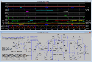
Random tests ::

src :: a noise amp test turns out to be a resolute op-amp models' quality checker !!!


src :: ADC related Op.-Amp. Experiment


The collector load regulator is another good test to find out some possible stability issues . . .
. . . nothing in particular irregular about this OpAmp ("ver.α Fix") was discovered in the following circuit


[Eop]

Monday, January 7, 2019

Updated the uA776 component level model

. . . The 3-rd test ::


about CLM-s' differences ::


about Virtual GND - Test ::


After some more tests . . . it turns out the only credible variant is the v.µA


. . . however if i manage to fix the v.1.1 problem it'll be the best . . . if (yay,yay,yay) . . . well if you fix one problem it usually triggers the load of others . . .


[Eop]

Saturday, January 5, 2019

incomplete (non-regulated) switched LED regulator designs

emerged in response to a latest local blackout event + a realization that the 77% of the energy would go "smoking in to the air" on the current limiting resistor e.g. the light would be ON some 3.3x less than otherwise . . . (but in the case of no (any) light even ←that would do ...)

1-st ) -- the step-down¹ with the separate regulation of voltage and current -- a case study ::


  • ↑ yields the 39% (and worse ...) efficiency for given setup ↑
  • ↓ has an unwanted startup overload spike ↓
    (might be removed by delaying/modifying the 555 startup)


2-nd ) -- the step-down² using the proven (Hi-Power) switcher variant (@ Lo-Power) -- gives a slight step in efficiency  but requires adding the output load or redesigning controls (such as using the lower power mos-Fet or Bjt ) --and/or-- adjusting the inductor ~ switching-frequency -- to get the efficiency higher


3-rd ) -- the step-up.. (← in my experience has statistically shown to have greater efficiency than the step-down conversion) ..using a commercial switching controller -- has a most promising(/preferred) result here . . . considering i didn't spent much time on fine tuning the following setup -- it does however have an unwanted startup over-spike (that may damage the LED-s on a "wrong day" or in case of too frequent power cycling)


SUM ) -- two last variants compared


PS ! ) -- as the title says -- !!! all these designs are functionally incomplete !!! -- e.g. :: not set to handle various specific situations , such as : too high input , too low input , output short , reverse polarity , switch/inductor failure ,  etc. ...

+Plus ) -- Couple of things to compare the prev. against . . .

1 ) -- an experimental converter (is lacking the control module -or- a concept for)


2 ) -- basic , simple -- linear regulator


3 ) -- basic , simple -- Op-Amp v. PNP versus NPN input stage


4 ) -- basic , simple -- Op-Amp v. PNP input stage (target LM324 or other Quadruple Op-Amp)


5 ) -- basic , simple -- linear regulator (for target input of 8x AAA to aged or not full 7A·h 12V PbSO₄)


[Eop]