Tuesday, December 20, 2016

Misc.

Rewired the old 3V Li-Cell-Button battery fed X-mas decorations -- those batteries are not cheap and have a too low capacity for LED-s . . . also i just got an unused Nokia AC-3E charger !
Theres 2 figures in series connection (2x  LED-s -- 1 per figure) -- since the least energy gets lost that way -- here what got implemented :

the next i found too complex to build for this simple task (where actually a properly chosen resistor would do fine . . .) -- but i wanted to check the circuit in action (which i rarely do) -- so the above v.1 worked fine with no modifications required (with 1Ω resistor as originally designed for 14mA actually drawing 10mA -- no much difference -- the dimmer might be and better as it won´t "jump into your eye")
... the creep itself ... in action XD ...
. . . the crystal balls´re not from the original set . . .

i actually researched the cc design-line further for Op Amps as i attempted to control 555 charging cycle as shown below . . .
. . . and the best results (for misc. cc - sink) gave the next weird setup (no good for PWM or pulsed setup)

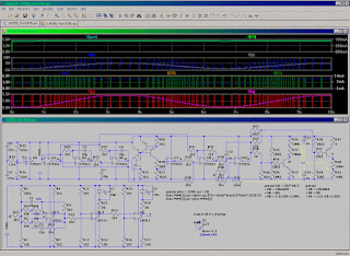
C-MOS - op. amp. capacitor charge control - a concept design . . .
! update 2017.01.04 17:08 UTC+2h ↑↑
(with no big difference)

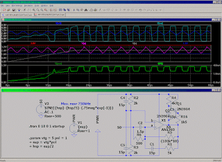
unusual use of 555 timer in phase shift osc. setup . . . the modulation input - has no desired effect here - coz lowering the upper trigger level dis-balances the charging currents that'd need to be cc sourced - but for 500kHz i didn't wanted to extend the test for here . . .


update 2016-12-21 14:38 UTC+2h (-2h UTC) ::

opti´ng the timer out of the circuit ???
 ? there seems to be no lower limit but the capacitors´ manufactured and what you can afford


[Eop]

Friday, December 16, 2016

LMx39 CLM Test

since the Philips didn't provided the internals we assume it's about LMx39 ! ???


Capabilities . . . ! Optimistic . . .


The next requires a fixed supply , no aging / temperature drift of the components (or very complex / fast auto adjust to . . .)


[Eop]

Thursday, December 15, 2016

555 component level model test

555 as RS trigger


555´s behavioural model Ring Counter ?? 5MHz


555´s component level model Ring Counter


Self-loop-back Oscillator . . .


. . . finding the limits


Re-trigger from timing capacitor


Re-trigger from merged threshold inputs


Re-trigger from low going output


Simple PWM -- there´s a Clock triggered CC v. of it in a prev. post -- but the CC clock triggering showed out multiple problems with this component level model (which are more easy to overcome using hardware other than 555 timer) . . .


[Eop]

Friday, December 9, 2016

PWM Test

Pulse width modulator based on LM311


Resistor adjusted


Automated - Sine-wave drived


Functional description ::
  • LM311 :: U1 - voltage to PWM modulator , U2 & U3 - LED drivers
  • LM324 :: U9 - Supply median , U4 - OpAmp´s virtual ground (internal to self) , U5 & U6 - Quadrature oscillator , U7 & U8 - Level shifter (for crap Cos outp by LM324 "OpAmp?") , U10 - LM324/Cos(αt) to R2R extender (for a Spice experiment)


Pulse width modulator based on NE555 - from datasheet


. . . revised (Update!)


. . . as i realized the most likely principle of operation of this modulator on datasheet for this crap to work right requires the modulating voltage to be pre-adjusted to inverse function of :
f(m) = m^(1 + Pi × m) . . . ? lets see . . .
exp(f()) = exp((1 + Pi × m) × ln(m) )
f() = (1 + Pi × m) × ln(m)
m = f.inverse(f().valueOf())
. . .
-- i guess my 311 PWM (in the 1-st & 2-nd circuit-fig. in this post) is a better choice
. . .
checked the backgrounds of the prev 555 PWM v. "failure" -- added constant current charging , adjusted capacitor/modulation vtg. threshold levels . . . seems working


to adjust the circuit to operation the lowermost modulation vtg. level must be set so that the break per clock still occurs ... and the capacitor value so that at the uppermost mod.vtg. level the break occurs before each next clock (requires 2-ch scope or a digital error detector -- perhaps such where clock increases the counter and OUTP resets it -- so whenever the count reaches 2 the capacitor value is too big)


[Eop]

Tuesday, December 6, 2016

Old Op Amp test PPM dcVC check

5V operation of LM358


pulse position modulated direct current switching voltage converter QC

! likely source® http://www.24vpower.com/dianlutu/89.html
converting it to 20V to 5V variant


. . . adjusting switch turnoff time ... down to about ~ 100ns


no further checks (e.g. output short circuit , load steps , starting at mild overload ... )


[Eop]

Sunday, December 4, 2016

К554СА3 component- versus LM311 behavioural model

null

(in simulation) tested up to 2.5MHz
К554СА3 starts operating ?normally below 1MHz

[Eop]

Tuesday, November 22, 2016

concept design of the switching dc voltage inverter

it seems the fast comparators are the soul of the whole thing - replaced the fast op amps coz they failed at various cases


uses 2N3906 2N3904 2N7002 BSS84 - not especially optimized or tuned for anything specific - no real life testing ... !
[Eop]

Wednesday, November 16, 2016

3V constant current LED Flasher concept designs

the 2N2222 2N2907 1N4148 1N5817 based White LED (with 3+ V voltage drop) flashers - occasionally utilizing the Red LED-s as zeners

constant current mode up to 2.5Ω -
a SUM of the internal resistances for 2x 1.5V batteries

constant current mode up to 2.2Ω

note! : that these are concept design simulations that are not been optimized nor built/tested in real

[Eop]

Sunday, November 13, 2016

Switched capacitor voltage tripler revisited

it seems te heart of the thing is a decent driving signal
extends http://chpsndtch.blogspot.com.ee/2014/10/switched-inductorless-dcdc-converter.html

all transistors and diodes are respectively
2N2222 2N2907 1N4148 1N5817

there's not much time wasted to optimize this circuit - just ran the concept test

the output should likely be additionally regulated and the converter set to run at demand (the output drops below certain threshold) by an electronic control (all of which were not included in this setup)


[EoP]

Friday, November 11, 2016

yet another 1.2V supply

Dif. Amp. Draft design:


Dif. Amp. to Op. Amp. - with overshoot shunt:


New concept with a short circuit limit and indication:


[EoP]

Shockley Diode , Tunnel diode , SCS SCR - BJT alternates study

Shockley ::

Dev. :


Low Voltage Neon Tube Replacement for ring counter:


Optimizing Hysteresis Curve:


Voltage pass over detector::


the following circuit may be possible to dev. further to a low speed tunnel diode variant:


Shockley to SCR ::


SCR RAM cell:


SCR Binary Counter:


[EoP]

Tuesday, November 1, 2016

Low Voltage SCS Counter Experiment

. . . integrated the www resource (poor) with my past experimental Lo voltage SCS designs . . . to just about get a working theoretical "New One" -- the 2 things marked on a fig. tell us that such is not likely to succeed in practice ...


actually i was playing around with oscillator designs the SCS-s in mind -- the cool feature about this thing (scs) is like some modern GHz MOSFET counters also DRAM e.c. those things can be designed to use practically no current and then shift 'em to another state by a narrow pulse

so, while i achieved my next osc. i studied in parallel an old electronics book - came across with ?? neg. triggered ring counter ?? thought to investigate it , improved the "CLK" shown in book for 1.2V supply . . .


after no success with the counter i actually realized that the TYPE of a counter i'm using for my improved CLK uses the pos. going pulse . . . yo!

. . . usually i finish what i started so the 1.fig. of this post actually shows the finished 1.2V design

for incase i'd ever need such in practice - i converted it to higher vtg. v. where the SCS is more likely to operate in realistic supply range . . . -- the ▼ "signal forward continuity test" ▼


► what's it made of ▼▼


it's tricky to get the signal out from low power "oscillators" -- here's one possibility :


PS! -- as the simulation in Spice may perform up to 1000x better than the actual circuit in real then it's not recommended to rush blindly building large systems composing them from the unknown / not studied designs
-- it's about 1 to 1k x that averages to ²√(1·1000) = 30dB = apx. 32x in general (more usually it's about 10x - maybe coz i ban the designs that perform worse ...) -- to get this right -- say if your 10Vdc PSU design has a simulation peak error ±24µV then in real device the appropriate value is to be expected ±24mV -- so it's 1000x change in relative error . . . as ±24mV/10V is ±0.24% then the common understanding of 1k x performance drop can't be grasped right without knowing the preceesding

 -- it's also why i don't build much of the stuff -- coz it takes testing separate stages . . . 1 by 1 . . . also verifying similar (same circuit) stages built from real components (with deviating parameters) that usually ends up in narrowing the operating ranges . . . without all possible fancy lab equipment in hand it takes more time than there is available . . .

... e.g. if you find such (SCS counter) interesting you have to perform further development-testing with (/based on) the real components you have in hand for such . . . before attempting to integrate it to any larger application !!!

[Eop]