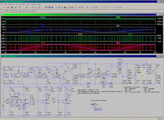
Resistor adjusted
Automated - Sine-wave drived
- LM311 :: U1 - voltage to PWM modulator , U2 & U3 - LED drivers
- LM324 :: U9 - Supply median , U4 - OpAmp´s virtual ground (internal to self) , U5 & U6 - Quadrature oscillator , U7 & U8 - Level shifter (for crap Cos outp by LM324 "OpAmp?") , U10 - LM324/Cos(αt) to R2R extender (for a Spice experiment)
Pulse width modulator based on NE555 - from datasheet
. . . revised (Update!)
. . . as i realized the most likely principle of operation of this modulator on datasheet for this crap to work right requires the modulating voltage to be pre-adjusted to inverse function of :
f(m) = m^(1 + Pi × m) . . . ? lets see . . .
exp(f()) = exp((1 + Pi × m) × ln(m) )
f() = (1 + Pi × m) × ln(m)
m = f.inverse(f().valueOf())
. . .
-- i guess my 311 PWM (in the 1-st & 2-nd circuit-fig. in this post) is a better choice
. . .
checked the backgrounds of the prev 555 PWM v. "failure" -- added constant current charging , adjusted capacitor/modulation vtg. threshold levels . . . seems working
to adjust the circuit to operation the lowermost modulation vtg. level must be set so that the break per clock still occurs ... and the capacitor value so that at the uppermost mod.vtg. level the break occurs before each next clock (requires 2-ch scope or a digital error detector -- perhaps such where clock increases the counter and OUTP resets it -- so whenever the count reaches 2 the capacitor value is too big)
[Eop]


No comments:
Post a Comment