Here's the grid - simulated fine (actually excellent -- that's why the design's revisited . . .) in prev. (a non TEST) v. but it didn't regulate "at all" in a real build -- here "we" possibly identified why -- if the R1 is too high (too little load) the VZ may go high thus also VT climbs out of the range and - bam! - we have a multiples of higher voltage on output than it's expected (the RED outlines the voltage regulation logic) ::
Next - omitting the CC module + startup chain - simplifies the design but we loss a magnitude of precision ::
Here follows a very poor example of a step-dn swithing regulator - asctually i didn't preserve the original v. of it (this is a fast feature restoration) coz i could not clear/filter the unwanted ringing and simulates extreamly slow . . . however the feature is a "built in" PPM (a pulse position modulation) capability (extra to low control current capability) -- needs a lot more testing to get it near right . . . (notice the varying supply internal resistance -- is why the efficiency graph wont link up exactly) ::
Omitting the VT reference point results in additional precision loss . . . but it revealed some specific behaviours of this type of regulation scheme (some of which're mentioned on o figure) ::
Here we've a near max low control current scheme - it starts auto-limit it's output current (depending on input supply) @ 150...200mA (output current max 235mA -- SC current 238mA) . . . and it seems to use some 110µA for regulation . . .
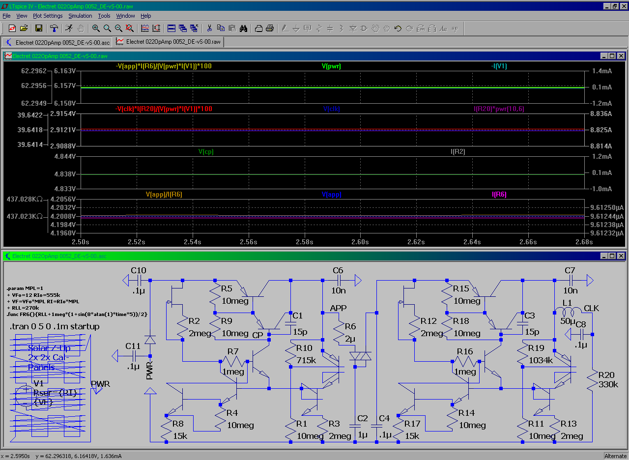
. . . a big deal considering the Solar battery test design with avg. 10.5µA TOT.supply draw - 8.8µA load current = 1.7µA (16%) regulation current . . . ::
. . . while the "near max low" v. ↑↑ has 108uA / 18mA avg. = 0.59% ( 120µA / 83mA peak = 0.15%) regulation currents


No comments:
Post a Comment